In recent years, with the rapid development of China's cities. The number of urban population and the number of private cars owned by the citizens are increasing year by year, which makes the urban traffic congestion worse and worse. The traffic congestion situation has become a common problem faced by large and medium-sized cities in China, and the problem of people suffering from the car caused by congestion has plagued everyone. At the same time, the environmental pollution phenomenon is also very serious.
This article refers to the address: http://
According to the overall research level of vehicle positioning technology at home and abroad, it can be concluded that the existing positioning technology has its own advantages and disadvantages. According to the current research on vehicle positioning technology, the best solution is to select the data solutions of multiple systems and then obtain the best solution according to the appropriate algorithm according to the appropriate algorithm. At present, the city is developing rapidly, people are becoming more and more dependent on public transportation, and the requirements for the quality of transportation services are getting higher and higher. If the arrival information and vehicle information of the bus can be timely and accurately notified to the people waiting for the bus, It plays an important role in alleviating the congestion of station personnel during the peak hours of commuting. By installing the information on the bus stop station, the information prompt system will provide the people waiting for the bus with the arrival time and the time of the passengers on the bus, and also know the approximate arrival time of the next bus. Passengers who are waiting for the bus can prepare in advance according to their own needs and provide convenience for passengers.
1 system design
The system adopts ZigBee wireless sensor network technology to timely and accurately reflect the specific location of the bus to the computer system of the bus dispatching station and timely release it to the driving route site, so that passengers and dispatchers can drive the bus on the current line. And the distribution situation is mastered. The passenger can understand the driving information of the current vehicle; the dispatcher can arrange and schedule according to the real-time running data of the vehicle. When an emergency occurs (such as traffic jams, vehicle damage, etc.), the dispatch center can make more reasonable scheduling arrangements and effectively avoid the phenomenon that the bus driver will leave early.
The intelligent bus system can estimate the time to reach the next station based on the location of the vehicle and the average speed of the vehicle. The location information of the bus is transmitted to the bus stop through the ZigBee network and displayed to the passenger through the electronic display, so that the passenger can know the information of the vehicle to be taken at any time; at the same time, the position information is finally transmitted to the dispatch center through the forwarding of the ZigBee node for the dispatcher. Dispatch and assign vehicles. In this system, the vehicle positioning and tracking technology can be used to understand the distribution of passenger flow on the line, and provide a basis for formulating the travel schedule. At the same time, it can effectively solve the current situation of bus operation and improve the vehicle management level.
2 system hardware design
The hardware platform of the intelligent bus system is composed of CC2430/2431 chip, gateway system, wireless reference node and positioning node. The wireless positioning mechanism is used to locate the traveling vehicle and collect and forward the positioning data.
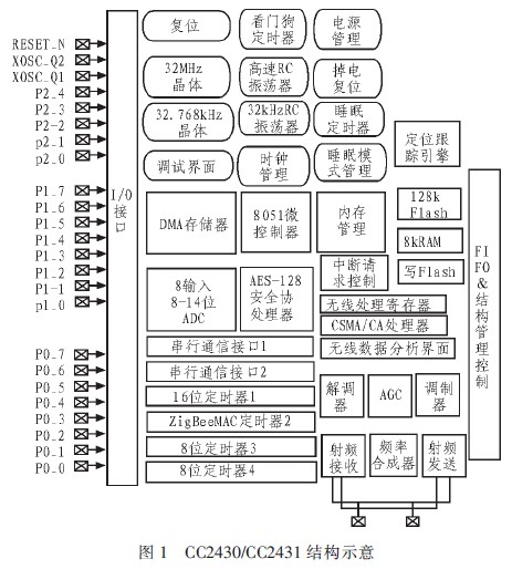
2.1 ZigBee wireless positioning microcontroller CC2430/CC2431
The CC2430/CC2431 chip is developed on the basis of the CC2420 chip architecture. The microcontroller, memory and ZigBee RF front end are integrated on the chip, as shown in Figure 1. Mainly by an 8-bit MCU (8051), 32/64/128KB programmable flash memory, 8KB RAM, analog-to-digital converter (ADC), timer (Timer), AES128 coprocessor, 32 kHz crystal with sleep mode Timer, watchdog timer, brownout detection circuit, power-on reset circuit and 21 programmable I/O pins.
2.2 Gateway System
The gateway system includes a backplane and a CC2430 ZigBee module. The bottom plate has a graphic Chinese character LED liquid crystal display, a ZigBee wireless module interface, an adjustable resistor, an LED, a keypad, a power interface, and an RS-232 interface.
2.3 Wireless Reference Node and Positioning Node
The module contains CC2430/CC2431, which is a ZigBee wireless network module conforming to the IEEE802.15.4 standard. The CC2430/CC2431 module has the physical layer and hardware layer of ZigBee/802.15.4, and can realize wireless communication of data through the physical layer and the media access control sublayer.
2.4 ZigBee Wireless Positioning System
ZigBee wireless positioning system consists of two parts: wireless positioning network and PC monitoring software. In this system, the wireless positioning network node adopts the CC2431 chip with hardware positioning engine function and the CC2430 chip with routing function produced by TI/Chipcon. The wireless positioning network is mainly composed of a terminal node, a reference node and a gateway node;
3 system software design
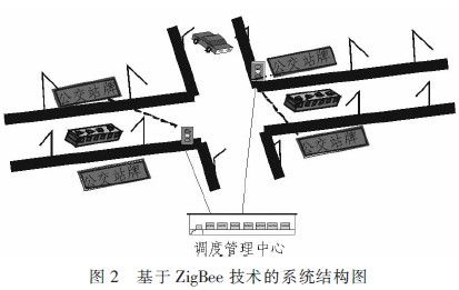
3.1 Intelligent bus system lower position machine design
The overall design of the intelligent public transport system structure is shown in Figure 2. The CC2431 chip with the positioning engine function is deployed on the bus. At this time, the CC2431 acts as a terminal node in the entire wireless positioning network. The CC2430 chip is deployed on both sides of the bus line and on fixed traffic facilities such as bus stop signs and street lights. The CC2430 acts as a reference node in the wireless positioning network. The gateway node is deployed in the dispatch center and connected to the server of the dispatch center through the RS232 serial data cable. First, the reference node automatically forms a network system with self-organizing characteristics, and starts to send its own position coordinate information and RSSI value to the terminal node. After receiving the information of the nearest reference node, the continuously moving terminal node calculates its own coordinates through its own positioning engine and sends it to the gateway node in the network. After receiving the data, the gateway node uploads it to the upper computer for further processing. If it is necessary to perform dispatch management on the bus, the dispatching center may issue instructions to direct the dispatching of the vehicle.
3.1.1 Intelligent bus system terminal node workflow
The nodes in the intelligent public transportation system include a terminal node, a reference node, and a gateway node. The terminal node is a positioning node. After receiving the RSSI value of all reference nodes in the positioning area, the terminal node calculates its own coordinate position through a positioning algorithm. The coordinate position of the reference node is a fixed value, but does not participate in the positioning calculation. A positioning area usually consists of 8 reference nodes. CC2431 is used as the positioning node, CC2430 and network expansion board are combined to form a gateway system, and finally connected to the computer through the serial port on the expansion board. The terminal node calculates the coordinate position of the node based on the RSSI value sent by the reference node in the location area. Figure 3 is a flow chart of the operation of the terminal node.
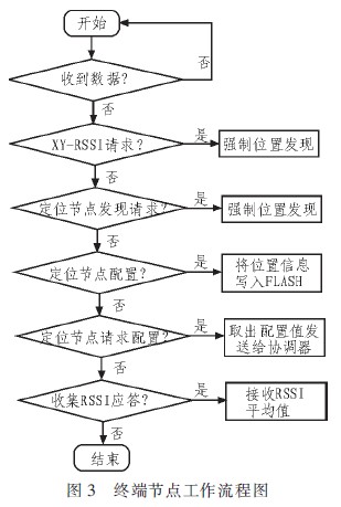
After transmitting the connection request in the network, the terminal node communicates with the reference node closest to itself, and calculates its own coordinate position according to the coordinate values ​​and RSSI values ​​of the reference node and according to the input parameters (A, N). This coordinate information is sent to the gateway node and finally transmitted to the server of the dispatch center through the RS232 serial data line.
3.1.2 Intelligent bus system network layer design
The intelligent public transportation system network layer is mainly responsible for the functions of data transmission such as networking and routing. In the network of intelligent public transportation system, there are mainly three types of data: data is sent from the bus to the central node, data is sent from the station node to the central node, Data is sent from the central node to the station node.
The main function of the network layer is to complete the forwarding of data. The network layer data service entity service access point completes the transfer of application protocol data units (APDUs) between the peer application entities; the network layer management service entity service access point completes the transfer of command frames between the upper layer and the network layer management service entity.
3.2 System PC software design
The intelligent bus system PC software is developed by Visual C++6.0 platform. The upper computer software is divided into serial communication module, data receiving module, data processing module, data display module and data saving module. After the data is transmitted to the PC through the RS232 serial port data line, the upper computer software completes the display and processing of the data.
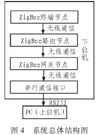
The intelligent public transportation system consists of two parts: the lower computer and the upper computer. The lower computer mainly includes the hardware modules CC2431 and CC2430, and the data is transmitted through the wireless positioning network, thereby avoiding the trouble of wiring. The host computer is developed with VC6.0 and has a friendly interface. It is a data monitoring and storage center. As shown in Figure 4.
4 test
The man-machine interface is mainly used to complete the information interaction with the user. Through the display of the interface, the vehicle information received by the serial port is displayed to the user, and the user analyzes the information to effectively manage the operation and scheduling of the vehicle. Therefore, it is very important to design and implement a friendly and convenient human-machine interface during the development of this system. The completion of the entire framework and human-machine interface work makes the subsequent development work more organized.
Figure 5 shows the vehicle information inquiry interface of the intelligent public transportation system. From the figure, the vehicle ID can be seen. Which line is currently passing through several stations.
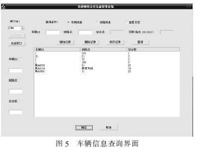
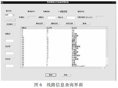
Figure 6 shows the line information query interface of the intelligent bus system. The name of the line, the station number and the name of the station can be seen from the figure.
In this paper, the overall design of the host computer software is divided and the overall function of the system is divided. The communication protocol, database and modules used in the system are analyzed and discussed. A feasible monitoring system is designed and implemented in the system. Key technologies are explained. Finally, after the system is implemented, the functional test and simulation test of the upper computer are carried out.
5 Conclusion
ZigBee is a low-speed, low-cost, high-reliability wireless communication technology. In this paper, the traffic problem of the current congestion is analyzed, and the environment of the current public transportation system is analyzed. Finally, the intelligent public transportation system platform based on ZigBee technology is designed and implemented. The system can accurately transmit the specific location of the bus to the dispatch center and timely release the data to the electronic display of the platform through the dispatch center, so that the passenger and the dispatcher can timely grasp the specific location of the bus. The real-time monitoring of the vehicle by the dispatch center can effectively complete the scheduling and arrangement of the vehicle. The experiment proves that the system can run stably and efficiently, and has certain application value.
The self-adhesive fabrics are coated with PTFE and have a layer of silicone or acrylic adhesive. The silicone adhesive fabric have a continuous operating temperature range between -70℃ and +240℃. The acrylic adhesive fabrics serves from -40℃ and +150℃ while it offers a very high initial adhesive power and a excellent solvent resistance.
Characteristics:
·easy to apply
·excellent high temperature resistance
·waterproof
·non-poisonous


Adhesive Tapes
Adhesive Tapes,Sealing Plastic Film,Sealing Adhesive Tape,Double Sided Adhesive Tape
TAIZHOU YAXING PLASTIC INDUSTRY CO., LTD , https://www.yaxingptfe.com