The choke-free CAN transceiver enables system designers to reduce the size of the CAN bus implementation while reducing the cost and complexity while meeting stringent automotive EMC requirements. ![]()
This article refers to the address: http://
As the density of electronic components in automobiles increases year by year, we need to ensure that the in-vehicle network maintains high performance in terms of electromagnetic compatibility (EMC). In this way, when different subsystems are integrated into a larger solution and run in a common (noisy) environment, these subsystems will function properly. Although there are many different in-vehicle networking standards and automotive OEMs have many different requirements for EMC, this article focuses on a topic that has proven to be particularly challenging: a controller LAN (CAN) Radio frequency (RF) emissions from the bus.
CAN uses balanced differential signaling to transmit baud rates up to 1 Mbps (or higher, provided that the "Flexible Data Rate" variable is used). Ideally, the use of differential signaling avoids all external noise coupling. Since each half-difference pair (called CANH and CANL) is symmetrical when changing, the interference caused by their noise is destructive. However, no CAN transceiver is perfectly ideal, and the low value asymmetry between the CANH and CANL signals produces a differential signal that is not fully equalized. When this happens, the common mode component of the CAN signal (the average of CANH and CANL) will no longer be a constant DC value. Instead, it will exhibit noise associated with the data.
Two major types of imbalances can cause this noise. One of them is the mismatch between the steady state common mode voltage levels during the dominant (driven) and recessive (high impedance) states.
This steady state mismatch will result in a noise pattern similar to the scaled version of the CAN data itself. This noise pattern is broad in its spectrum and appears as a series of discrete spectral lines that extend to very low frequencies and are evenly spaced. A timing mismatch can result in a noise pattern consisting of short pulses or interference that appears as long as there is an edge transition in the data. The spectral content of this noise pattern tends to concentrate on higher frequencies.
The waveform in Figure 1 shows a common mode noise that can be observed on the output of a typical CAN transceiver. In this image, the black trace (channel 1) shows CANH, the purple trace (channel 2) shows CANL, and the green trace (data function) is the sum of CANH and CANL. This summation process gives a waveform whose value is equal to twice the common mode voltage at a specified point at this time.

Common mode waveforms show two types of noise: high frequency noise corresponding to dominant to recessive/recessive to dominant transitions, while low frequency noise corresponds to dominant and recessive common modes that do not match.
Since the common mode portion of the signal can be coupled to other components in the system (or to the external system) (through radiation or conduction paths), this common mode noise directly affects the radioactivity. Conducted emissions from this device are measured in accordance with Industrial Engineering/Electronics (IBEE) Zwickau's engineering services; as shown in Figure 2, the device's conducted emissions are combined with an ordinary automotive original equipment manufacturer (OEM) limit line. Draw together.
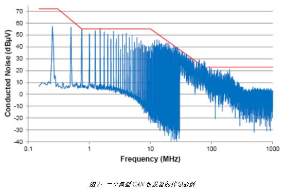
The output of this transceiver radiates beyond the OEM requirements in the low and high frequency regions. In order to reduce the radiation to a satisfactory level, some external filtering must be used.
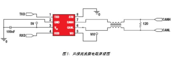
The most common filter component in the CAN bus is the common mode choke (shown in Figure 3). The common mode choke is constructed by winding two coils on the same core. In terms of the arrangement of the direction of each coil winding, the common mode current (that is, the direction of the current in each coil is uniform) has a magnetic flux sharing the same polarity. This allows the common mode choke to operate as an inductor for the common mode signal, providing an increased impedance with increasing frequency. Conversely, differential mode currents (that is, opposite current directions within each coil) will cause their magnetic flux to interact with the reverse polarity. For an equalized waveform such as a CAN signal, the magnitude of the opposite magnetic flux in each coil will be equal, so no static flux will accumulate in the core. This allows the choke to operate as a short circuit for the CAN signal.
This technology is very effective in reducing CAN bus emissions. For example, when a 51μH common mode choke is used to retest a device that does not meet the emission requirements, performance is greatly improved (Figure 4).
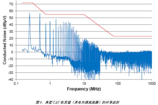
However, there are some disadvantages when adding a common mode choke. A significant disadvantage when using common mode chokes is the extra space required on the printed circuit board and the extra bill of materials cost. However, in addition to this, some minor effects on the CAN bus should be considered. Since the choke coil introduces some series inductance, this inductor generates resonance when combined with the parasitic capacitance of the CAN network. Although common mode noise is reduced in most frequency bands, these resonances cause an increase in the amount of noise at the resonant frequency. This effect can be observed in the common mode noise waveform shown in FIG.
-
Safelock Protection: Automatically shuts off power if errors are detected.
-
LED Light Indicators: Displays if there are any issues with the GFCI or if it needs to be placed.
-
Easy Installation: 2 Pole/3 Wire-Grounding with Wall Plate and pre-installed Mounting Screws. Install in as little as 15 minutes!
Receptacle UL
Receptacle UL,UL Receptacle Photocell Socket,UL Industrial Receptacles,Photocell Socket UL
Hoojet Electric Appliance Co.,Ltd , https://www.hoojetgfci.com