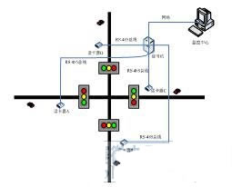
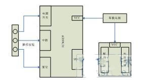
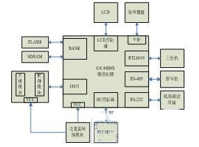
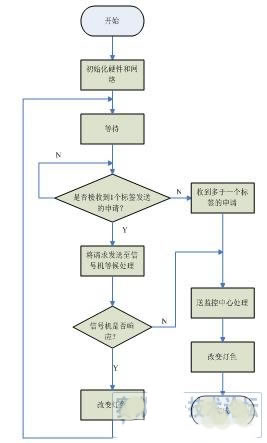
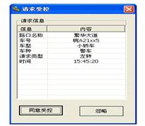
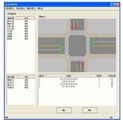
0 Preface This article refers to the address: http:// Some special-purpose vehicles can often be seen in daily life. When these vehicles pass through intersections, they are often changed by the traffic police to temporarily change the color of the traffic lights or directly through the relevant personnel to obtain the intersections. Priority access. This approach is not very good in real time and security. Radio frequency identification is a non-contact automatic identification technology. It automatically recognizes the target object and acquires relevant data through radio frequency signals, works without human intervention, and can recognize high-speed moving objects with fast and convenient operation. Various harsh environments. The system can effectively identify the application issued by the special vehicle, and determine whether it obtains the priority right of the intersection through the control of the traffic signal control machine or the remote monitoring center at the intersection. The monitoring center can also obtain the road traffic conditions within a certain range and the surrounding area according to the feedback information of the vehicle, thus providing a strong basis for regional coordinated control and decision-making of road traffic. 1. System design requirements and overall design Figure 1 System schematic The hardware platform of the system mainly includes two parts: a radio frequency identification (RFID) electronic tag module and a radio frequency identification card reader module. The electronic tag module is mounted on the vehicle and is generally located at a convenient location for the driver to operate. Taking into account the cost performance and development cycle factors, the electronic tag part of the microcontroller uses the US ATMEL company's 51-core based microcontroller AT89C51 [1]. According to the power supply mode, RFID tags can be divided into active and passive. Active means that the battery is provided with power in the tag. The distance is long, but the life is limited, the volume is large, the cost is high, and it is not suitable for harsh environments. Work under; no battery in the passive tag, use beam power supply technology to convert the received RF energy into DC power supply for the internal circuit of the card, its working distance is shorter than the active card, but the service life is long and the working environment is not high [ 2]. Considering that the working environment of the tag is in the car, and in order to improve the signal quality and the working distance, the electronic tag module of the system adopts an active tag. The electronic tag module is powered by the vehicle power supply. The card reader module is located at the intersection. It uses the ARM7TDMI-S core-based 32-bit microprocessor S3C44B0X from South Korea's SAMSUNG company to transmit the identified information to the traffic signal control machine at the intersection via the RS-485 bus, or through the network port. The information is transmitted directly to the upper computer of the monitoring center, and then the traffic signal control machine or the monitoring center determines whether to change the state of the signal light. Four card readers are installed at each intersection, all on the right side of the road. To prevent card reader misreading, place four card readers in a safe location far away from each other. 2. Hardware design Figure 2 Electronic tag structure block diagram The electronic tag adopts the nrf2401+AT89C51 architecture. Nrf2401 is the RFID chip of NORDIC semiconductor. It adopts the global open 2.4GHz frequency band and has 125 channels, which can meet the needs of multi-frequency and frequency hopping. It has high data throughput, speed up to 1Mbps, and fewer external components. A crystal oscillator and a resistor can be used to design the RF circuit. All operating parameters such as transmit power and operating frequency can be set by software. The power supply voltage ranges from 1.9V to 3.6V. The power consumption is very low, the current consumption is very small, and the output power is -5dBm. The typical peak current is 10.5mA, and there is a special voltage regulator circuit inside the chip. Therefore, any power supply (including DC/DC switching power supply) has good communication effect, and each chip can be set up to 40bit address through software. And the data will be output only when the local address is received, and the built-in CRC error correction hardware circuit and protocol. The AT89C51 is a low-power, high-performance 8-bit microcontroller with a 4K-byte Flash erasable read-only memory on-chip. It uses CMOS worker ants and high-density non-volatile memory technology for central processing. The device is composed of ALU, special register group, timing control component, etc. It has strong functions of calling, jumping, judging, rich data transmission, and providing intermediate results and common parameter registers. The electronic tag is mounted on the vehicle. The operation panel consists of five buttons, which are switch, reset, left turn request, right turn request and straight line request. The request key adopts an interrupt mode, and is used to send a priority access request to the card reader when the vehicle approaches the intersection and needs to pass preferentially. The tag also stores information about the vehicle, such as the type of vehicle, license plate, model and purpose. Figure 3 card reader system block diagram The reader system still uses nrf2401 as the receiving node. The card reader part mainly implements information recognition and communication functions. Adopt SAMSUNG's ARM7TDMI-S core based high performance 32-bit microprocessor S3C44B0X [3]. Its operating voltage is only 2.5V, which greatly reduces the power consumption of the chip. It can expand SDRAM, FLASH, and the built-in LCD controller can support up to 256-color STN LCD[4], 71 general-purpose I/O, including 8 An external interrupt source. The system extends the RTL8019 of Realtek's 10Mbps Ethernet interface chip. The chip has a 16-bit data line interface and a 20-bit address line interface. It can automatically add a frame header, a frame start delimiter and a physical frame on the transmitted physical frame. Checksum. The card reader transmits the received information to the traffic signal control machine on the site through the RS-485 bus, and directly changes the state of the traffic light. If there is the same or higher application level in the intersection, the request information is sent to the monitoring through the network port. The center arbitrates, and then the monitoring center sends instructions directly to the signal [5]. 3. Software design In order to realize TCP/IP communication and make the system as lightweight and compact as possible, the system is implemented by transplanting the LwIP protocol stack on the uC/OS-II operating system. lwIP is an open source TCP/IP protocol stack implementation from the Swiss Academy of Computer Science. It is a lightweight open protocol stack designed for embedded systems. Under the premise of maintaining the basic requirements of the TCP/IP protocol, LwIP avoids many cumbersome copy processing by sharing memory between layers, which greatly saves code and data storage space, and is therefore very suitable for embedded applications. Different from other lightweight protocol stacks, LwIP not only supports general network protocols, such as UDP protocol, DHCP protocol, PPP protocol, but also supports multiple network interfaces, IPv6 and standard APIs. 3.1 LwIP transplantation on uC/OS-II For uC/OS-II [6] and ARM's ADS compiler, LwIP porting only needs to write three files in the arch folder - cc.h, sys_arch.h and sys_arch.c. Among them, cc.h has definitions related to CPU and compiler, including data structure and size storage. In order to enhance portability, LwIP puts together the operating system-related data structures and functions to form an operating system encapsulation layer, providing a unified interface for operating system services such as timing, process synchronization, and messaging. The operating system implements a specific operating system encapsulation layer, which is implemented by sys_arch.h and sys_arch.c. Sys_arch.h mainly defines the data structure related to the operating system - semaphore, mailbox and process number. These have corresponding entities in uC/OS-II. The mailbox in LwIP corresponds to uC/OS-II. message queue. The definition of the operating system-related functions in sys_arch.c, including the initialization of the system and the operation of the signal and mailbox - create, delete, deliver and wait, these functions need to be re-encapsulated with the corresponding functions in uC / OS-II . In addition, many functions of timers are required in the TCP/IP protocol stack. In LwIP, the sys_timeout structure queue and corresponding functions are implemented. Each sys_timeout structure includes the timeout length of the thread, and the function of the sys_arch_timeouts() function in the callback handler sys_arch.c after the timeout is to return the head pointer of the sys_timeout structure queue corresponding to the current process. The method used by this system is to create an array of sys_timeout structure pointers according to the maximum number of LwIP processes during system initialization. After each LwIP process is created, its priority is assigned from a continuous known interval. sys_arch_timeouts() function The priority of the process is obtained by calling the OSTaskQuery() function to obtain the head pointer of the corresponding sys_timeout structure queue. 3.2 RTL8019 driver preparation The work done by the RTL8019 driver is mainly the initialization, sending and receiving of Ethernet packets of the 8019. The initialization function rtl8019_init() is called by the netif_add() function when adding an Ethernet interface. The global network interface structure corresponding to this interface is first initialized during the call, and then the function registers of the 8019 are set. After the 8019 is initialized, the arp_init() function is called to start the ARP function, and then the sys_timeout() function is used to start the timer of the ARP buffer list life cycle. The sending of the data packet first finds the destination MAC address from the ARP buffer queue, then constructs the header of the Ethernet data frame, and finally calls the underlying transmission function low_level_output() to send the data frame. If the corresponding IP/MAC entry is not found, an ARP request data frame is sent. The reception of the data packet is called by the interrupt [7] handler rtl8019_ISR(). Its execution process is to call the lowest receiving function low_level_input() to receive the data frame from 8019. If the IP packet is received, the ARP buffer is updated. The queue passes the packet to the function specified by the network interface structure for processing. If the ARP packet is received, it is processed by the etharp_arp_input() function. The bottom-level receive and send functions use 8019's remote DMA mode of operation to improve performance [8]. 3.3 Software Block Diagram Figure 4 card reader system software block diagram The response level of the signal is set by the upper computer of the monitoring center. The signal can change the color of the lamp autonomously if it is authorized in advance. If it is not authorized in advance, or if multiple requests for different tags are received at the same time, the information must be It is sent to the monitoring center for processing, and the upper computer of the monitoring center determines the priority and then sends the command to control the action of the signal. The monitoring center can also obtain information such as the location of the specific vehicle and the road conditions in the area at any time, and achieve the purpose of regional coordinated control by reasonably changing the green letter ratio of the signal in the area. 4. Experimental results The PC software of the monitoring center was developed by Mircosoft Visual C++.NET 2003. The system is applied to the intersection of the bustling avenue and the Jinxiu Avenue in a municipality. Since the preset is controlled by the monitoring center, when the label sends a pass request, the card reader will send a request to the monitoring center, and the host computer of the monitoring center pops up the dialog box shown in FIG. 5, which shows the intersection where the vehicle is located. The vehicle number, model, type of vehicle, type of request for access, and request time, etc., the monitoring center decides whether to process its request, and the monitoring center operator can click "Ignore" to not respond to the current application of the vehicle. Figure 6 PC software control interface After clicking "Agree to Control" in the dialog box of Figure 5, the setting window shown in Figure 6 will appear. The upper left corner is the main road list in the Science City area, and the lower left corner shows the traffic signals corresponding to the roads. In the current state, the signal that is not online is not displayed. The upper right corner is the schematic diagram of the intersection of the bustling avenue and the Jinxiu Avenue where the vehicle currently sending the application is located, and the execution plan of the current intersection signal is set by the list in the lower right corner. The current implementation scheme is as shown in the list. The intersection signal currently performs a four-phase scheme, and the lamp group number of each phase is as shown. The current implementation is the No. 1 time slot scheme, which corresponds to this signal. The No. 1 scheme indicates that the day is divided into two periods: 7:00 to 21:00 and 22:00 to 6:00. The phase timing of each time period is different. . The latter time is the length of time for each phase of the current time period. The time of release can be set by changing the length of time. 5. Summary The system is applied to the actual intersection, which makes the passage of special vehicles more convenient and convenient, and greatly reduces the labor consumption. As part of the intelligent transportation system, the system also has certain practical significance for realizing regional coordinated control. references: [1] Song Tingqiang, Shen Jianliang, Qu Yingjie. Design of Digital Part of RFID Electronic Label[J].Journal of Qingdao University of Science and Technology,2008,29(1):72-76. [2] FINKENZELLER K. Radio Frequency Identification Technology [M]. Wu Xiaofeng, Chen Dacai, Trans. Beijing: Publishing House of Electronics Industry, 2006.36-125. [3] Li Yan, Rong Panxiang. Based on S3C44B0X embedded uClinux system principle and application [M]. Beijing: Tsinghua University Press, 2005: 69-254. [4] Chen Wei, Yu Shenglin. Interface design and MiniGUI implementation of LCD module based on ARM[J]. Chinese Journal of Scientific Instrument, 2007, 28(Z4): 277-281. [5] Ma Lianbo, Su Weixing, Hu Yuyuan, et al. Electronic signage design based on embedded Linux and RFID technology[J]. Journal of Computer Applications, 2007, 27(12): 283-285. [6] Najia. The transplantation of embedded real-time operating system uC/OS-II on Sharp LH79520 processor [J]. Measurement and Control Technology, 2007, 26 (10): 53-56. [7] Feng Wei, Yu Xiaofeng. Implementation of Image File Execution and Interrupt Operation Mechanism Based on ARM System[J]. Journal of Computer Applications, 2006, 26(Z1): 255-257. [8] Zhang Penghe, Wang Qun, Zhang Donghui. Interface Design and Programming Skills of RTL8019 Controller and High Speed ​​Digital Signal Processor[J]. Foreign Electronic Components, 2006, 10(8). 47-49.
Quality is the soul of a company, we strongly belive that safety is the first of the battery. Our IPhone 7 Battery use brand new veken, Amprius or other famouse brand rechargeble cell pone battery cell, it is high capacity, durable and saftety. The protection circuit we use TI chip, so it haven't any influence after iphone IOS update. We produce all model Iphone Battery Replacement from iphone 4 to iphone X, It is widely used in cell phone after-sales maintenance service and IPhone Battery repair.
Iphone 7 Battery,Apple 7 Battery,Iphone 7 External Battery,Apple Iphone 7 Battery Shenzhen Hequanqingnuo Electronic Technology Co., Ltd. , https://www.hqqnbattery.com