Chen Jingfeng, Fan Sanlong, Sun Jinhua, Bao Suli, Nanjing Guodian South Rail Transit Engineering Co., Ltd. With the rapid development of electrified railway construction and the improvement of production automation, with the wide application of Ethernet communication technology and high-performance microcontrollers, the application of digital technology and the trend of digitalization are becoming more and more obvious; standardized communication protocols are generally supported; The software development of the language greatly improves the performance and reliability of the system. Society has increasingly high requirements for railway automation equipment. The real-time, reliability, and continuity of traction power supply have become one of the most important issues of concern to the entire society. In addition, with the development of communication network technology and power monitoring terminal data acquisition, With the enhancement of processing capacity, railway power users have higher and higher requirements for power supply quality, and in addition to accurately grasping the power data when the power network is in a fault condition, the power supply department urgently needs to monitor the existing power distribution and monitoring stations and the power is far away. On the basis of the mobile terminal, high-precision real-time monitoring and recording of the voltage and current quantities under normal and faulty operating conditions is required. The time scale of the recorded data is based on the system accurate clock and the time resolution of the fault time reaches milliseconds. In the conventional design of the power monitoring terminal, limited by the limitation of the communication network bandwidth, the measurement amount is generally sent to the threshold at the minimum time resolution of 1 S, and is sent to the loop at intervals of 20 to 60 seconds during the steady state of the load. The measurement data has low time resolution and no time scale. In the conventional power SCADA system or substation monitoring system, in the curve history data storage of the master station or the monitoring system computer, due to the use of fixed time resolution, limited by the capacity and processing capacity of the database, the data preservation interval can generally only Achieve 1min. The final recorded historical data has low resolution and poor time accuracy and cannot meet the above new requirements of users. The intelligent terminal uses network and high-performance single-chip technology to break the bottleneck of information flow in the real-time monitoring system, thereby fundamentally improving the real-time performance of the system. . In addition, the hardware and software design is planned to adopt a standardized and open concept, so that the system's function expansion and redundancy backup can be easily realized, and the software's reliability and portability will also be guaranteed. To sum up, the development of this project has the following three purposes [1]. 1) With the development of traction power supply, urban rail transit, and power industry automation, the demand for power supply automation is getting higher and higher. The current measurement and control terminal equipment can no longer meet some advanced users in terms of overall structure, performance indicators, and measurement and control capacity. Needs. 2) Currently, the measurement and control terminals in the field of traction power supply automation are single-network communication modes of traditional single-CPU monitoring and control devices. The time resolution of load curve achieved by the popular 32-bit single-chip MC68332ACFC20-based CPU can only be 20ms, and the load curve is recorded. A single method, at the same time, CPU processing power, response speed, etc. can no longer meet user needs. 3) At present, some products in the foreign technology level that are close to the intended target of the smart terminal have been flooded into the Chinese market. Domestic counterparts are also carrying out similar development work. As the backbone enterprise of power automation, we naturally cannot give up this promising market. . In other words, the fierce market competition makes the intelligent terminal have urgency. From the system structure design, this solution product tends to be independent of the functional modules, which facilitates the flexible use of the configuration according to requirements, and minimizes the coupling of the module to facilitate the expansion. At the same time, the device processing capacity has been greatly improved, providing a complete integrated automation solution for unattended traction substations. The remote control intelligent terminal of the microcomputer is a multifunctional measurement and control device designed for real-time monitoring of voltage, current, power, etc. of the traction power supply system and the railway power distribution system. It chooses the high-performance MCU as the communication main CPU, DSP is the AC sampling CPU, and has the functions of AC sampling measurement, digital input, pulse input, control output and network communication. The remote control intelligent terminal of the microcomputer consists of a chassis, AC and DC input and sampling modules, a CPU module, a DSP module, an open module, an open module, a switch power module, a motherboard, and a liquid crystal monitor panel. Sampling and measurement data processing hardware block diagram shown in Figure 1. The DSP is the core of the real-time load curve formation. It performs data sampling processing and digital filtering of the mutation, threshold crossing and circulation modes. The MCU is mainly responsible for data queue buffering, sending and local storage of data recording files. The hardware components, module design, software design, and function implementation of the smart terminal will be described below with reference to the drawings. 1.1 Hardware Composition and Module Design The block diagram of the intelligent terminal is shown in Figure 2. Main module hardware design: 1) AC/DC input and sampling module: This module provides 18 voltage input and current input loops for protection and measurement. After the AC volume is transformed, it is sent to the DSP module through low-pass filtering, sample and hold, and multiplex conversion. . Intelligent terminal sampling and measurement data processing see Figure 2. The device can be configured with up to four ac/sampling modules. Each module can be flexibly configured according to engineering requirements. 2) CPU module (ie, master CPU module): The master module is the core module of the device, which consists of a single-chip microcomputer system, Ethernet components, CAN network communication management components, serial communication management components, and terminal maintenance components. The main control module consists of POWERPC main CPU, 128M SDRAM, 288M FLASH, Ethernet communication interface, CAN communication interface, serial port and GPS interface. The high-performance microprocessor CPU (POWERPC), large-capacity FALSH (288Mbyte), and SDRAM (128M byte) make this CPU extremely capable of data processing and can implement various complicated troubleshooting functions. The POWERPC main CPU is the core of this module and is responsible for handling the entire data processing and control. In addition, the serial port communication management unit adopts dual 100M Ethernet interface and dual 1M internal dedicated CAN network design. The internal communication of the device adopts the CAN-BUS network without corruption priority arbitration as the communication network for the module to realize the main control module and each subunit. Module data exchange, complete telemetry, remote signaling, remote control, remote adjustment, remote pulse, recorded wave, GPS time and other functions. The CAN network works in a multi-master mode. Any sub-module can actively initiate information transmission to ensure the real-time and reliability of important event information transmission. The module can be connected to a substation automation system or a remote dispatch system via the network; it can also be connected to a PC, and various remote tests, remote debugging, and remote upgrades can be performed on the device using a dedicated debugging software package installed on the PC. 3) Opening the module and opening the module: The device can be configured with up to 8 modules for opening and opening, and the opening/out module configuration can be flexibly selected. The opening module is 24V opening mode, and each module can be connected to 32 channels. Each module can provide 12 sets of switches (ie, 24 channels). 4) Monitor MMI panel: This module consists of CPU, RAM, ROM, Flash Memory, Serial EEPROM and hardware clock. It is responsible for keyboard processing, liquid crystal display, protection message storage and communication with substation automation systems, etc., 1Mbyte capacity The Flash Memory can record the fault report with the recorded waveform data and enter into the dislocation event. This information is not lost when the DC power of the device disappears. 5) Power Module: Provide five sets of regulated power supply for other modules of the device. 6) DSP module: This module adopts DSP chip technology to sample, calculate, analyze, and judge the analog signal converted from the AC module. At present, a DSP module can access up to four AC modules, which can simultaneously collect up to 72 analogs, collect 32 points per cycle analog wave, calculate the fundamental RMS value for 5 ms, and calculate the first harmonic value for 20 ms. . 7) Chassis modules: Use standard 6U structure chassis. It can be flexibly applied to various occasions. With strong scalability and flexibility. 1.2 Software Design 1) The CAN network without corruption priority arbitration is used as the internal communication network [2]. It operates in a multi-master unbalanced manner. Each I/O node can initiate the information transmission initiatively to guarantee the transmission of important information such as switch position. The real-time nature. The internal network can be configured as master-slave hot backup mode on the interface and bus to improve reliability. Use interrupt service routines to accept data interruptions, accept task analysis, and send data tasks. When the master module sends a request data command to the slave module, the slave module generates a data interrupt. After entering the service program to protect the scene, and then the CPU alone accept the contents of the buffer command task analysis, according to the task analysis results to determine the data sending task, and send data to the main module, and finally reply to the scene, interrupted return. 2) The internal network communication protocol is layered, and the connection-oriented datagram service is provided at the transport layer to improve efficiency. When necessary, part of the information at the application layer is confirmed and retransmitted to ensure reliability. 3) In order to achieve complex management in the network environment and facilitate programming, all nodes will be equipped with real-time multitasking operating system software, and all network interface software will be standardized and unified. 4) The device can use the 10M Ethernet TCP/IP protocol to communicate with the outside, and it also provides expandable multi-serial multi-protocol external communication functions. 1.3 Functional implementation The software design of the smart terminal adopts a real-time multitasking operating system to implement the scheduling and management of tasks such as various acquisition and control [3], which not only improves the running reliability of the software, but also has better scalability. Software takes a standardized, reusable approach. The main implementation features are: 1) Limit recording. The device measures the three-phase AC RMS of each circuit. The effective value is compared with the user's fixed value for each loop. After reaching the set value and satisfying the delay condition, the 100 points (20 ms between points and points) before and after the time of the overrun will occur. The three-phase voltage and current rms data are recorded and can be uploaded to the main station system as a file, which also supports local reading. Limit judgments include: over-voltage, under-voltage, and over-current. Each setting has two setting values, and each setting value has a corresponding delay value. For all setting values ​​and delay values, remote or local reading and modification are supported. The over-limit judgment function can be enabled and disabled locally and at the schedule. 2) Fault recording. Fault recording includes manual recording and fault recording. Manual recording can record normal waves, fault recording only for current loops, overcurrent, fast-break recording, and slope recording. The current slope recording is a 1/4-cycle (5ms) algorithm that reflects correctness. Action current. The event record will record and store the trigger time, event type, and related parameters, and record the five weeks before the trigger point, and the waveform waveform of the sampled waveform after the last five weeks. Each cycle collects 32 points, in a file format. Upload scheduling, recording functions can be allowed and prohibited locally and scheduled. You can set the switching action and parameter over-limit as the trigger condition. Once a certain condition is met, event recording or waveform recording will be triggered. 3) Load curve. The load curve function is used to record the voltage and current RMS curve in the line 24h. The time resolution of the curve is up to 5ms. The device uses a time-scaled telemetry to describe the 24h load curve. When the load is stable in the time interval, one sample point is recorded every 30s. When the load change exceeds 2% of the rated value (the threshold value can be set), one sampling point is recorded every 1s. When a sudden change in voltage or current is detected, it is 5ms. For time resolution, the RMS values ​​for the first 5 points and the last 10 points were recorded in real time. The device has a maximum of 256M bytes of solid-state storage and can record curve data for a minimum of 24h. The curve data can be saved locally, analyzed offline, or sent to the monitoring or scheduling master station in real time. The master station forms the 24h curve data. 4) In-line nuclear phase function. The device has a voltage phase sequence error (positive sequence/negative sequence reverse) alarm and two circuit voltage different period (out-of-phase) alarm function. When the loop is a voltage loop and the three-phase voltage rms value is greater than 60%Un, if the positive sequence (or negative sequence) is calculated, the negative sequence (or positive sequence) angle difference is displayed. After the delay, an alarm is generated and an event is generated. Record; Under the same conditions as above, calculate the angle difference of any corresponding line voltage of the two loops, if the angle difference exceeds -30. ~30. Range, after the delay alarm and generate two-phase voltage different period (out-of-phase) alarm event records. 5) Automatically determine the line fault with the master station. Through the telemetering value, the fault signal is judged and sent out and quickly reported to the dispatching master station. The automatic fault determination function of the line fault is performed in cooperation with the master station to provide the necessary conditions for effective fault isolation. 6) Remote and local maintenance. The device provides a powerful maintenance analysis system software. The portable device installed with the software can be connected to the device through the Ethernet interface, which can achieve the device settings, parameters of the modification, solidification and other operations, can be read into the state, to achieve Switch remote control operation, read device failure and wave recording report, read device log file. The intelligent terminal of this project has carried out many innovations such as high-capacity, high-performance, distributed, and network-type on integrated monitoring and control terminals in the field of integrated automation of electrified railways, rail transit and substations, and changed the design concept of traditional single-CPU monitoring and control devices. The modular design, distributed and bus control network multi-CPU monitoring and control terminal design of the device is realized. Compared with the current mainstream communication management devices from several manufacturers, there are obvious advantages: the intelligent terminal main control module uses a high-performance microprocessor CPU (POWERPC), large-capacity FALSH (288Mbyte), SDRAM (128Mbyte) makes this The CPU has strong data processing capabilities and can implement a variety of complex fault handling functions; processing capabilities lead the same products to ensure stable and reliable operation of the system; commercial embedded operating systems, load curve time resolution can reach 5ms, but also more able to meet Users need high standards for real-time performance. This scheme adopts a new real-time load curve construction method to achieve real-time monitoring and recording of voltage and current under the normal and fault conditions of the power supply network. The data recording time scale is based on the device clock, and the time resolution at the time of change reaches 5~20ms. The data recording adopts dynamic time resolution, and uses mutations to detect local recorded waves instead of traditional data compression algorithms. It has the advantages of small amount of calculation, small amount of data, adaptability, and versatility. The formed load history data can be saved locally, analyzed off-line, or combined with a monitoring computer or SCADA master station that supports this function, enabling real-time recording of the load curve and meeting the requirements of user load monitoring and failure analysis. The device has good portability and maintainability; modular structure of software and hardware, flexible customization according to different application requirements, easy to implement and maintain and upgrade the project, and provides a complete integrated automation solution for unattended traction substations. As an important part of the company's new generation of power supply automation system products, this program product has passed the provincial and ministerial level appraisal. The appraisal conclusions are: the design is reasonable, the function is complete, and the overall technical performance has reached the international advanced level. The intelligent terminal has been successfully applied in the fourth electric integration project of the Guangxi Coastal Railway Expansion and Reconstruction Engineering Station. It is currently the main product of the company in the traction power supply automation system and has a broad application prospect. The intelligent terminal hardware uses a high-performance MCU as the communication master CPU, and the DSP is an AC sampling CPU. Software design innovation adopts new load curve recording method (this method has applied for patent for invention and received 201110295343.1), which meets the real-time requirements of load recording, improves the time resolution of fault time, and reduces data transmission and The amount of storage, the device can be widely used in electrified railway traction substations and various voltage grade power substations, power distribution, outdoor box change, on-column switches. It has been successfully applied to projects such as Guangxi Coastal Engineering and Zhuoli Line. Under the current background of traction and subway projects, this product will surely create good economic benefits. Single Burner with Built in Hob Single Burner Gas Stove,Stainless Steel Surface Hob,Single Burner Gas Cooktop,Single Burner Gas Hob xunda science&technology group co.ltd , https://www.gasstove.be
Keywords: substation; network type; intelligent terminal; POWERPC; FALSH
1 Plan implementation 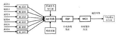
Figure 1 Block diagram of intelligent terminal sampling and measurement data 
Figure 2 The functional block diagram of the intelligent terminal
2 The beneficial effect of this program
3 Conclusion
references
[1] Jia Limin, Zhang Xidi, Cai Xiusheng, et al. Railway Transportation Automation - Status Quo, Problems and Challenges [C]. Proceedings of the China Control Conference 1994, 1994.
[2] Yu Kuanming. CAN bus principle and application system design [M]. Beijing: Beijing University of Aeronautics and Astronautics Press, 1996.
[3] Yu Haisheng, et al. Microcomputer Control Technology [M]. Beijing: Tsinghua University Press, 1999.