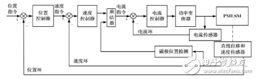
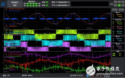
With the continuous improvement of industrial automation, the rapid development of servo control technology, power electronics technology and microelectronic technology, servo motion and control technology are also maturing. The motor motion control platform has been widely used as a high-performance test method. Application, people's requirements for servo performance are also constantly improving. 1. The first is the current loop. The loop is completely inside the servo driver. The Hall device detects the output current of each phase of the driver to the motor, and the negative feedback gives the current setting PID adjustment, so that the output current is as close as possible. Constant current, current loop is to control the motor torque, so in the torque mode the driver's operation is the smallest, the dynamic response is the fastest. 2. The second loop is the speed loop. The negative feedback PID is adjusted by the signal of the detected servo motor encoder. The PID output in the loop is directly set by the current loop, so the speed loop control is included in the speed loop. Ring and current loop, in other words, any type of chess must use a current loop. The current loop is the control's follow-up. At the same time of speed and position control, the system actually performs current (torque) control to achieve speed and position. Corresponding control. 3. The third ring is the position loop. It is the outermost ring. It can be considered that the construction between the driver and the servo motor encoder can also be built between the external controller and the motor encoder or the final load, which should be determined according to the actual situation. Since the internal output of the position control loop is the setting of the speed loop, the system performs all three loop operations in the position control mode. At this time, the system has the largest amount of calculation and the slowest dynamic response speed. Figure 1.1 1. The speed loop mainly performs PI (proportional and integral), and the ratio is the gain, so we need to adjust the speed gain and the speed integral time constant to achieve the desired effect. 2. The position loop mainly performs P (proportional) adjustment. For this we just need to set the proportional gain of the position loop. When the position mode needs to adjust the position loop, it is best to adjust the speed loop first. The parameter adjustment of the position loop and the speed loop has no fixed value. It depends on the mechanical transmission connection mode of the external load, the movement mode of the load, the load inertia, and the pair. Speed, acceleration requirements, and the rotor inertia and output inertia of the motor itself are determined by many conditions. The simple method of adjustment is to adjust the gain parameter from small to large in the range of general experience according to the external load. The integral time constant is from large. To the minor, set the steady-state value without vibration overshoot to the optimum value. Figure 1.2 1. MES-100 motion control platform consists of motor and loading system, motor driver debugging system, data acquisition and power system. From the motor to the drive to build a complete hardware and software experimental environment, providing a fully open software and hardware interface, with a rich and scalable teaching experience, can do motor identification, stall, motor efficiency test, motor parameter measurement, motor TN curve Test, motor motion control and encoder vector torque, non-inductive vector speed analysis, etc. The test results are shown in Figure 1.3 below. 2. The speed and torque control of the servo motor are controlled by the analog quantity. The position control is controlled by the pulse. If there is no requirement for the speed and position of the motor, the constant torque mode can be adopted. Changing the analog setting to change the set torque can also be achieved by changing the value of the corresponding address by communication. If there is a certain progress requirement for the position and speed, the speed or position mode can be adopted. The position control mode generally determines the rotation speed by the externally input pulse frequency, and confirms the rotation angle by the number of pulses. It has strict control over speed and position, and is widely used in the industry. Figure 1.3 The optical module (optical module) is composed of optoelectronic devices, functional circuits and optical interfaces. The optoelectronic device includes two parts: transmitting and receiving.
Simply put, the function of the optical module is to convert the electrical signal into an optical signal at the transmitting end, and after transmitting through the optical fiber, the receiving end converts the optical signal into an electrical signal.
The optical module is an optoelectronic device that performs photoelectric and electro-optical conversion. The transmitting end of the optical module converts electrical signals into optical signals, and the receiving end converts optical signals into electrical signals. Optical modules are classified according to the packaging form. Common ones include SFP, SFP+, SFF, Gigabit Ethernet Interface Converter (GBIC), etc.
The transmitting part is: the electrical signal with a certain code rate is processed by the internal drive chip and then drives the semiconductor laser (LD) or light-emitting diode (LED) to emit the modulated light signal of the corresponding rate. The internal optical power automatic control circuit makes The output optical signal power remains stable. Sfp Module,Scodeno Sfp Transceiver,Scodeno Optical Transceiver,Gpon Optical Sfp Module Shenzhen Scodeno Technology Co.,Ltd , https://www.scodenonet.com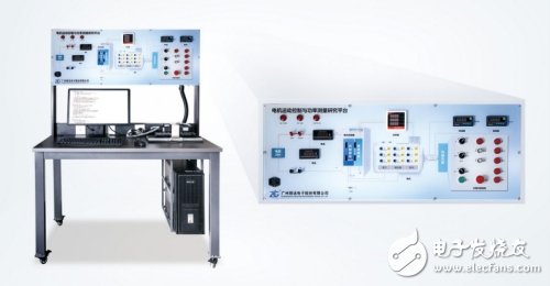

The receiving part is: the optical signal of a certain code rate is input into the module and then converted into an electric signal by the light detection diode, and the electric signal of the corresponding code rate is output after the preamplifier.