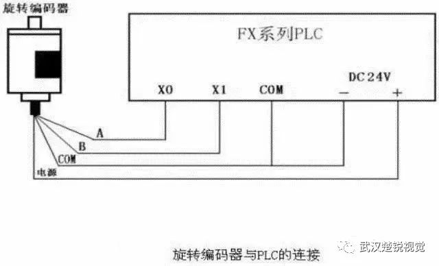
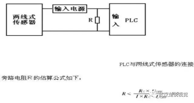
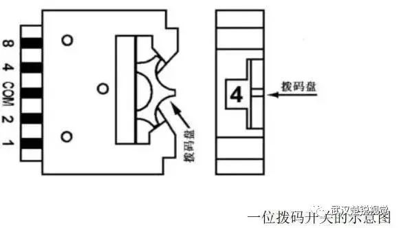
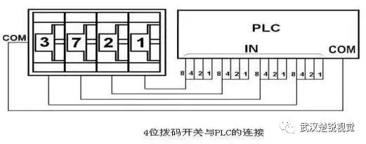
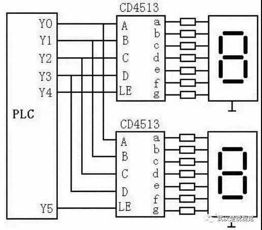
Common input components of PLC are buttons, travel switches, proximity switches, transfer switches, dial switches, various sensors, etc., and output devices are relays, contactors, solenoid valves, etc. Correctly connecting the input and output circuits is the prerequisite for ensuring the safe and reliable operation of the PLC. 1. Connect with main electrical components As shown in the figure below, it is a schematic diagram of the wiring to the input devices such as buttons, limit switches, changeover switches and other main electrical appliances. The PLC in the figure is a DC sink input, that is, all input points share a common terminal COM, and a DC24V power supply is provided in the COM terminal. For group input, you can also refer to the method in the figure below for group connection. 2. Connect with rotary encoder The rotary encoder is a photoelectric rotary measuring device, which directly converts the measured angular displacement into a digital signal (high-speed pulse signal). Because of this, the output pulse signal of the rotary encoder can be directly input to the PLC, and the pulse signal is counted by the high-speed counter of the PLC to obtain the measurement result. Different types of rotary encoders have different phase numbers of output pulses. Some rotary encoders output three-phase pulses of A, B, and Z, some only have two phases of A and B phases, and the simplest one only has A phase. As shown in the figure above, it is a schematic diagram of the connection between the rotary encoder outputting two-phase pulses and the FX series PLC. The encoder has 4 leads, 2 of which are pulse output lines, 1 is the COM terminal line, and 1 is the power line. The power supply of the encoder can be an external power supply, or it can directly use the DC24V power supply of the PLC. The “-†end of the power supply should be connected to the COM end of the encoder, and the “+†should be connected to the power end of the encoder. The COM end of the encoder is connected to the PLC input COM end, and the A and B two-phase pulse output lines are directly connected to the PLC input end. Pay attention to the response time of the PLC input when connecting. Some rotary encoders also have a shielded wire, the shielded wire should be grounded when using. 3. Connect with sensor There are many types of sensors, and their output methods are also different. When two-wire sensors such as proximity switches and photoelectric switches are used, due to the large leakage current of the sensor, the wrong input signal may cause the PLC to malfunction. At this time, the bypass resistor R can be connected in parallel at the PLC input terminal, as shown below As shown. When the leakage current is less than lmA, its effect can be ignored. In the formula: I is the leakage current of the sensor (mA), UOFF is the upper limit value of the PLC input voltage low level (V), RC is the input impedance of the PLC (KΩ), and the value of RC varies according to the input point. 4. Connect with multi-dial switch If some data in the PLC control system needs to be modified frequently, you can use a multi-dial switch to connect to the PLC and set the data outside the PLC. The following figure shows the schematic diagram of a one-digit dial switch. One-digit dial switch can input 0 to 9 of a decimal number or 0 to F of a hexadecimal number. As shown in the figure below, the 4-digit DIP switches are assembled together. Connect the COM terminals of the DIP switches to the COM terminal on the PLC input side. The 4 data lines of each DIP Switch are connected to the 4 input points of the PLC in a certain order. It can be seen from the figure that the use of DIP switches occupies many PLC input points, so this method is generally not used in occasions where it is not necessary. Connection of PLC and output element PLC switch output: Relay output: It can output AC and DC, wide voltage range, large current, low operating frequency, generally about 1Hz. Transistor output: can only output DC, generally below 30V, low current, high operating frequency, up to 200KHz or higher. Thyristor output: can only output AC, generally 60-450V, high current, high operating frequency, and expensive. Analog output are: Voltage output, generally -10V to + 10V voltage output. Current output, generally 0-20mA, 4-20mA current output. When the PLC is connected to an output device, the output points of different groups (different common terminals) may have different voltage types and levels corresponding to the output device (load), but the output points of the same group (same common terminals) may have different voltage types and levels Should be the same. According to the type and level of the output device voltage to decide whether to connect in groups. Take the FX2N as an example to illustrate the connection method between PLC and output device as shown in the figure below. The connection method in the figure is the case where the output devices have the same power supply, so the common terminals of each group are connected together, otherwise they must be connected in groups. The figure only shows the connection between Y0-Y7 output points and output devices, and the connection methods of other output points are similar. 1. Connect with inductive load element The output end of the PLC is often connected to an inductive output device (inductive load). In order to suppress the voltage generated when the inductive circuit is disconnected, the internal output elements of the PLC are damaged. Therefore, when the PLC is connected to an inductive output device, if it is a DC inductive load, a freewheeling diode should be connected in parallel at both ends; if it is an AC inductive load, a resistor-capacitor absorption circuit should be connected in parallel at both ends. As shown below. In the figure, the freewheeling diode can be selected with a rated current of 1A, a rated voltage greater than 3 times the power supply voltage; a resistance value of 50 ~ 120Ω, and a capacitance value of 0.1 ~ 0.47μF. The rated voltage of the capacitor should be greater than the peak voltage of the power supply. Pay attention to the polarity of the freewheeling diode when wiring. 2. Connect with seven-segment LED display The PLC can directly use the switch output to connect with the seven-segment LED display, but if the PLC controls a multi-digit LED seven-segment display, the required output points are many. In the circuit shown above, a chip CD4513 with latching, decoding, and driving functions is used to drive a common cathode LED seven-segment display. The data input terminals A to D of the two CD4513 share the 4 output signals of the PLC, where A is the lowest Bit, D is the highest bit. LE is the latch enable input terminal. At the rising edge of the LE signal, the BCD number input from the data input terminal is latched in the on-chip register, and the number is decoded and displayed. If the input is not a decimal number, the display goes off. When LE is high, the displayed number is not affected by the data input signal. Obviously, the number of output points occupied by N displays is P = 4 + N. If the PLC uses a relay output module, a pull-down resistor should be connected to each output terminal of the PLC connected to the CD4513 to avoid the input terminal of the CD4513 floating when the contact of the output relay is disconnected. When the status of the PLC output relay changes, its contacts may be shaken, so the data output signal should be sent first. After the signal is stable, the data will be latched into the CD4513 with the rising edge of the LE signal.
Toggle switches
Toggle switches, also called On Off Toggle Switches, is often used as the switching device of the equipment stalls. Meanwhile, we are also offer our customers Key Switches, Metal Switches, Automotive Switches, Push Button Switches, etc.
The Electrical Toggle Switches is a manually controlled Toggle Switches similar to the dial switch. Most of this Latching Toggle Switches are widely used in on-off control of AC and DC power circuits, and are less commonly used in circuits of several kilohertz or up to 1 megahertz. Let's take a look at the following.
1. Splash-proof knob button switch
The panel is installed with a splash-proof `O` ring seal, and the knob is a ball. It is a splash-proof ball button knob switch. Its terminals are in a straight line and the bottom of the terminals is sealed with epoxy resin. Strong corrosion resistance, suitable for automotive parts
2. Vertical Mount Right Angle Toggle Switch
The vertical mounting of the terminals and the terminal pins are right-angled, so it is a vertically mounted right-angled toggle switch. Its contacts are gold-plated and highly reliable. Mostly used in anti-theft devices, alert system.
3. Bipolar single toggle switch
At the same time, the switch breaks the phase line and the N line and controls one branch. Therefore, it is a bipolar single toggle switches. The contacts are in 3PDT form and are used for multimedia speakers and stereos.
4. Standard surface mount unthreaded toggle switches
The terminal adopts the standard mounting mode. Its sleeve has no thread. It is called a standard surface mount screw-less switch. The contacts are SPDT and its electrical life is as high as 55,000. Used for medical equipment
5. Horizontally mounted right-angle toggle switch
Compared to the vertical switch, it only changes direction to horizontal, so it is horizontally mounted right-angle toggle switch. The contacts are double-pole double-throw and the bottom of the terminal is Epoxy Seal. Mostly used for computer peripherals.
Toggle Switches,Toggle Switch On Off,Toggle Switch Autozone,Toggle Switch Home Depot YESWITCH ELECTRONICS CO., LTD. , https://www.yeswitches.com