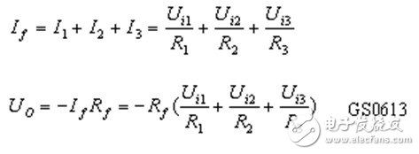
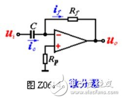
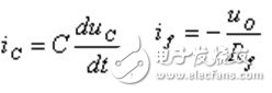
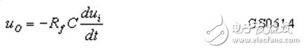
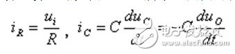
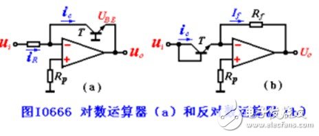
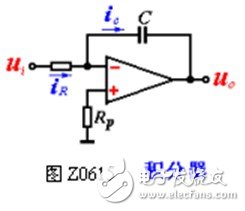
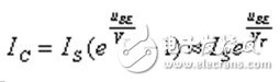
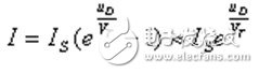
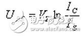
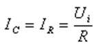
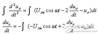
1. Adder Figure Z0613 The circuit has the function of adding input signals. According to the basic characteristics of the ideal op amp: Obviously, the circuit can add input signals to a certain proportion, so it is called an adder. When R1 = R2 = R3 = Rf, the above formula is simplified to UO = ï¼ (Ui1 + Ui2 + Ui3) Second, the differentiator The circuit is shown in Z0614, according to U + = U- and Ii = 0: U + = U- = 0 iC = if because, Therefore: It can be seen that the output voltage is proportional to the differential of the input voltage, and the differential operation is realized. 3. Integrator The integral operation circuit is shown in Figure Z0615. Available from the picture: Thus available: It can be seen that the output voltage is proportional to the integral of the input voltage, and the integral operation is realized. Four, logarithmic and anti-number arithmetic According to the volt-ampere characteristics of the semiconductor PN junction, logarithmic and antilogarithmic operations can be realized. Figure Z0616 (a) is the logarithm operator circuit. Under the conditions of UCB ≥ 0 and UBE> 0, IC and UBE have a precise logarithmic relationship within a relatively wide range. which is , Thus by This shows that the output voltage of the circuit is proportional to the logarithm of the input voltage, and the logarithmic operation function is realized. Similarly, from Figure Z0616 (b), we can get: This shows that the output voltage of the circuit is proportional to the exponent of the input voltage, and the exponential operation function is realized, that is, the function of the anti-log operation is realized. Using the combination of the aforementioned several operators can also realize multiplication, division, power and other operations. These types of operators are the basic units in analog computers. Example: Solve a differential equation using an adder and an integrator: Where uo is caused by Solution: The idea of ​​using the integrator to solve the differential equation is to integrate the high-order derivative of time with respect to the variable multiple times until the variable is obtained, and at the same time satisfy the coefficient given in the equation by selecting the circuit parameters. This question; The points on both sides are: The summation integrator is used to implement the above calculation, and the circuit is shown in Figure Z0617. A1 in the figure is the summation integrator, which is obtained after integrating the three terms on the right aluminium laptop stand amazon,vertical laptop stand india,vertical laptop stand multiple Shenzhen ChengRong Technology Co.,Ltd. , https://www.laptopstandsupplier.com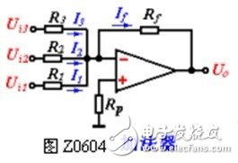
 Substituting into the above formula is:
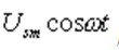
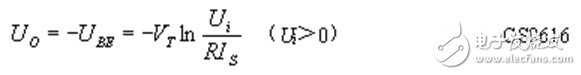

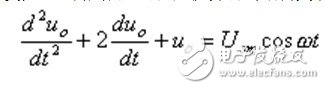
 The resulting output voltage is set to zero for all initial conditions.
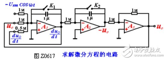
 Points
  , And then get uo, and
  Again by
  , Uo and
 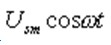 Sum up. According to this, the original equation can be transformed into:
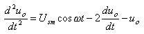
 , Pair A2
  Integrate again to get -uo, A3 is the inverter, and the output is uo. During the operation operation, first turn on K1 and K2 to discharge C1 and C2, thus achieving the initial condition. When joining
 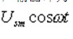 After that, you can observe the waveform of uo with an oscilloscope. This is the solution of the differential equation.