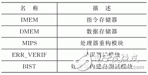
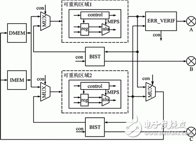
A two-mode redundant MIPS processor is designed based on two-mode redundancy technology and dynamic part reconfigurable technology of FPGA. The processor can use dynamic reconfigurable technology to repair system faults without interrupting the system operation; the stability of the system is ensured by setting redundant logic on important modules inside the system. The use of these two technologies makes the processor more reliable and longer lasting than other processors. The test results of the processor system on the Xilinx XC5VLX110T development board show that the processor can run normally. Field Programmable Gate Array (FPGA) is a hardware circuit reconfigurable electronic logic device based on SRAM. It can be programmed into the FPGA by programming the hardware configuration bit stream generated by the hardware description language. The logic has changed. The flexibility and versatility of FPGAs in electronic design has made them widely used in important fields such as aerospace, communications, medical and industrial control. However, hardware logic circuits in FPGAs are susceptible to SEU (Single Event Upset) and SETs (Single Event Transients) failures, resulting in system failure. FPGA circuit failure reduces the stability and longevity of an FPGA-based embedded system, while severely limiting its application in all aspects of production and life. System backup, system failure recovery, and system multi-mode redundancy are an effective way to prevent system failure. FPGA dynamic local reconfigurable technology is an emerging technology that can be applied to system fault recovery. It can dynamically change the logic function of some logic circuit blocks inside the FPGA while the FPGA system is running, without affecting other logic. The normal operation of logic; the two-mode redundancy technology is a typical system redundancy fault-tolerant design method. It sets up a backup module for important modules of the system to ensure stable and reliable operation when the system fails. Based on the above ideas, this paper designs a two-mode redundant MIPS processor based on FPGA dynamic reconfigurable technology. Xilinx's XC5VLX110T development board is an FPGA development board with ML509 chip and dynamic configuration capability of internal logic blocks. Verilog is a structured and synthesizable hardware description language that enables rapid implementation of structural-level system modeling of digital logic circuits. This paper uses Xilinx's XC5VLX110T development board as the system development platform, and develops a MIPS processor system based on the two-mode redundancy structure in Verilog language. The overall structure of the system is shown in Figure 1. The main components of the system are listed in Table 1. Table 1 Main components of the system IMEM is an FPGA built-in memory generated by Xilinx IP generator. Since the MIPS processor does not change the contents of the instruction memory during operation, it is designed as a single-port read-only memory without clock gating for MIPS processing. The instructions that the system will execute. IMEM has a data bit width of 32 bits and a memory depth of 1 024. DMEM is also a memory generated by the IP generator. It stores the data required for the execution of the MIPS processor. It is a read-write single-port memory with clock edge control and enable control. DMEM has a data bit width of 32 bits and a memory depth of 1 024. The MIPS module is a single-cycle MIPS processor with a complete data path, ALU, and control logic using the Verilog language description. Its instruction set size is 32, and all instructions are integer operation instructions. This processor module contains the instruction memory and data memory external interface, which is the system core module, so it is designed as a reconfigurable area in the FPGA. The ERR_VERIF module is a fault detection module that compares the execution results of two MIPS systems and generates corresponding fault control signals. The BIST module is also called a built-in self-test module. This module starts running only when the system fails. It is used to test the correctness of each subsystem and output test results. In Figure 1, the portion enclosed by the dashed line is the reconfigurable area in the FPGA. There are two reconfigurable areas in the figure, the previous area is the main subsystem area, and the lower area is the backup area of ​​the main subsystem area. Figure 1 Overall structure of the system After the system power-on reset, in the case that both MIPS internal logics are normal, the system execution process is as follows: the instruction memory fetches the instruction from the IMEM according to the instruction execution address after the system reset, and sends it to the two MIPS systems; two MIPS The processor completes the corresponding work under the instruction of the instruction, and then outputs the execution result to the ERR_VERIF module, DMEM and IMEM module; the ERR_VERIF module analyzes whether the system is running normally, and then outputs the analysis result information to the LED lamp A on the FPGA. When the internal logic of one of the MIPS processors fails, it can be assumed that the main MIPS area in the upper part of Figure 1 is faulty. The system execution process is as follows: ERR_VERIF The fault detection module detects that the sub-area of ​​the system is faulty, and then issues a fault location detection control signal; at this time, after receiving the detection control information, the BIST module starts the built-in self-test system and inputs the fault test vector. MIPS system. After the BIST module is turned on, the system's command input will no longer come from the IMEM module, but will be provided by the BIST module. At the same time, the execution result of the instruction will not be written back to the DMEM module, but will be fed back to the BIST module. MIPS operates on the test vector and feeds the result back to the BIST unit. The BIST unit is tested multiple times to ensure an accurate judgment of the fault. After the BIST obtains the execution result, it analyzes the test result and determines whether the current MIPS system is running normally. Finally, the analysis result is output to the LED lights B and C on the FPGA. KNB2-63 Miniature Circuit Breaker
KNB2-63 Mini Circuit breakers, also named as the air switch which have a short for arc extinguishing device. It is a switch role, and also is a automatic protection of low-voltage electrical distribution. Its role is equivalent to the combination of switch. Fuse. Thermal Relay and other electrical components. It mainly used for short circuit and overload protection. Generally, According to the poles, mini Circuit breaker can be divided into 1P , 1P+N , 2P, 3P and 4P.
KNB2-63 Miniature Circuit Breaker,Electronics Miniature Circuits Breaker,Automatic Miniature Circuit Breaker,Mini Circuit Breaker Wenzhou Korlen Electric Appliances Co., Ltd. , https://www.zjaccontactor.com
