FPGA technology allows the development of special hardware structures within a flexible design environment. Compared to the standard structure of microprocessors and DSP processors, this feature of FPGA gives designers a lot of freedom because it can build a special hardware structure to match a range of control performance and Implementation of the requirements of the limit. Therefore, considering that in order to protect the parallelism of all potential algorithms, these specialized structures are based on a perfect algorithm, which is the implementation of the matching control algorithm and the final hardware. However, in many cases, the design of FPGA-based control structures is too straightforward and requires designers to master several different knowledge (such as microelectronics, control, and electrical theory), especially in motor drives. The structure of the complex control algorithm. This naturally leads many designers to prefer to choose the standard processing solution of DSP. Therefore, in order to make the design of the control algorithm better manage and weaken the directness, the designer must strictly follow a set of steps and rules, that is, an effective design method. The main feature of this method is that it is common to many off-the-shelf designs, optimizing the consumption of resources and target components, while taking into account control performance, and finally, shortening development time. Several scholars have proposed a design approach that draws attention to everyone [22]-[26], and these are based on reusable and friendly development steps. This will be shown in the picture below. The special features of these plans are in the design of the fait accompli, but there is always doubt as to why the control engineer is not a microelectronics expert. The reason is that the design steps that are extremely important are successfully implemented in the Matlab-Simulink-friendly design environment. However, another key issue is to consider control performance, so the final hardware architecture requires optimal optimization. Therefore, the use of Matlab does not mean that the Very High Speed ​​Hardware Description Language (VHDL) [27] code can be automatically generated under the recommended toolbox provided by the major FPGA manufacturers, which has to be adopted in consideration of a series of resource consumption problems. Non-optimized solution. Therefore, in order to suggest a suitable solution, the designer has to describe his own algorithm structure with VHDL code, but he needs to be helped with the help of A3 [28] technology. As we all know, this A3 technology is the opposite of the two opposite needs, in other words: 1) there are good methods for non-professional designers can not pose a threat; 2) taking into account the need to control performance, will inevitably lead designers to design It takes a lot of effort in the process, but the main steps of the design method must be stated.
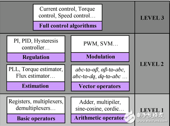
Module division of control algorithm This step is crucial in complex control algorithms. Its main purpose is to shorten the design cycle, which is "time to market." Its content includes dividing the entire control algorithm into smaller sub-modules that are easy to develop and have certain functional significance. These can be identified by several reusable and independent modules such as calibrators, modulators, estimators, and vector operators in terms of hierarchy and normative concepts [5]. Hierarchical concepts usually refer to the division of a large-scale and complex design into sub-modules that are more manageable, and the purpose of the normative concept is to maximize the use of existing design modules. At the same time, however, designers have to check the chosen algorithm - modular separation - to meet the integration specification. This specification requires certain procedures to be performed under the constraints of the hardware resources of the target device. Next, an optimization program plan [28] is described for this purpose, which will greatly reduce the utilization of hardware resources. Although each module is applied independently, the number of these modules is quite large, so considering the consumption of hardware resources, the performance level of the entire module will be reduced. Therefore, if the hardware configuration does not meet the requirements, the designer must reduce the number of modules, although some of the available field design modules are reduced. Different reusable modules have different levels of abstraction and can be proposed to be added to the control library of an electronic system. This library, although useful, is still under construction [29], as shown in Figure 12, which consists mainly of three different levels. According to the author's experience, these three different levels of modules can fully demonstrate the different functions of the electronic control system. The highest and lowest level modules include particle operators such as registers and algorithmic operators (adders, multipliers, etc.). The intermediate level modules include the most commonly used modules in the electronic control system, such as continuous PI controllers, PWM, vector conversion, etc. These modules are built using the first level of operator. Finally, the entire control algorithm forms the third or highest level module in the library.
[22] YA Chapuis, JP Blonde, and F. Braun, "FPGA implementaTIon by modular design reuse mode to opTImize hardware architecture and performance of ac motor controller algorithm," in Proc. EPE-PEMC Conf., Sep. 2004, pp. 134 – 142, CD-ROM. [23] T. Riesgo, Y. Torroja, and E. de la Torre, "Design methodologies based on hardware descripTIon languages," IEEE. Trans. Ind. Electron., vol. 46, no.1 , pp. 3–12, Feb. 1999. [24] M. Cirstea, “Electronic systems integrated modelling and opTImized digital controller prototyping—A novel (HDL) approach,†IEEE Ind. Electron. Soc. Newslett., vol. , no.3, pp.11–13, Sep.2005.[25]L.Charaabi, E.Monmasson, and I.Slama-Belkhodja, “Presentation of an efficient design methodology to develop IP-core functions for control systems: Application to the design of an antiwindup PI controller," in Proc. IEEE IECON, Seville, Spain, Nov. 2002, pp. 1942–1947, CD-ROM. [26] JCG Pimentel and H. Le-Huy, "A VHDL- Based methodology to develop high performance servo drivers," in Conf.Rec.IEEE IAS Annu.Meeting, Ro Me, Italy, Oct. 2000, pp. 1505–1512. [27] DLPerry, VHDL. New York: McGraw-Hill, 2004. [28] T. Grandpierre, C. Lavarenne, and Y. Sorel, “Optimized rapid prototyping†For real-time embedded heterogeneous multiprocessor," in Proc.CODES, Rome, Italy, May 1999, CD-ROM.[29]M.-W.Naouar et al.,IP-Cores Library.[Online].Available: u -cergy. fr/etud/ufr/composan/iupge/IP_cores/index.htm
Easy Electronic Technology Co.,Ltd , https://www.pcelectronicgroup.com