1 data link layer
The data link layer includes two parts: transmit and receive. This chapter mainly introduces the specific processing of the data stream from the data link layer entering the transmitter to the data link layer from the receiver and the modules involved.
Figure 21 and Figure 22 below are the internal structure diagrams of the transmit data link layer and the receive data link layer. This section will introduce the function of each specific module from the transmit link layer, and also include the receive link layer. The function of the module that is always sent by the module is relative, so when introducing the module in the transmission link layer, the function of the receiving part module will be introduced at the same time.
The data entering the link layer is mapped to the data frame at the transport layer, the data entering the data link layer is framed as the smallest unit, and the data link layer operates in the charcter clock clock domain, so after entering the data link layer, The farme data will first pass through the Frame_to_octet module, and the Frame_to_octet module will convert the input data frame into an octet data stream.
The data stream is scrambled at the Scrambler module, and the scrambling function is optional.
The scrambled data stream is byte-replaced by the alignment_character_generator module. The purpose of the byte replacement is to detect if the data channel data stream is working properly.
The Mux module selects the data stream that requires data through the TX_controller module.
The data stream will be encoded in the 8b/10bcoder module and finally output to the serdes_tx module.
TX_contrller is the control module of the data link layer. The module exchanges control information with the upper interface through the control interface, and analyzes the control information to control the workflow of the data link layer.
IniTIal_lane_alignment_sequcence_generator is a generation module for the synchronization sequence between different data channels. This module will generate the required synchronization sequence after the system starts synchronization.
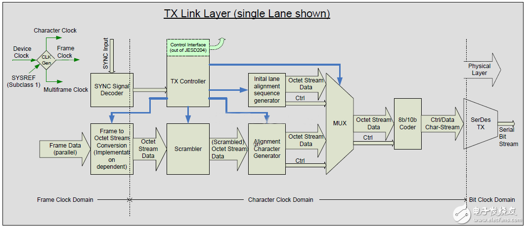
Figure 21: Internal structure of the data link layer transmitter
In the receiver part, the data stream layer data flow is as follows:
The physical layer serdes module converts the input 1-bit serial data stream into a 10-bit parallel data stream, and completes the alignment of the data stream through special alignment bytes, and decodes the aligned data through 8b/10b, and outputs Outputs an 8-bit wide octet data stream.
The data stream of the decoded output will pass the lane_alignment_buffering_detecTIon_monitoring module, which will judge whether the current data transmission is synchronized between different channels by checking the position of the calibration character in the data frame.
The data stream then passes through the Frame_alignment_detecTIon_monitoring module, which is also an error in whether the data frame is aligned by detecting the calibration character in the data frame.
After two levels of alignment detection, the data will enter the descrambler module for data descrambling.
The descrambled data stream will be newly combined into data frames and transmitted to the data transmission layer through the octet_to_frame module.
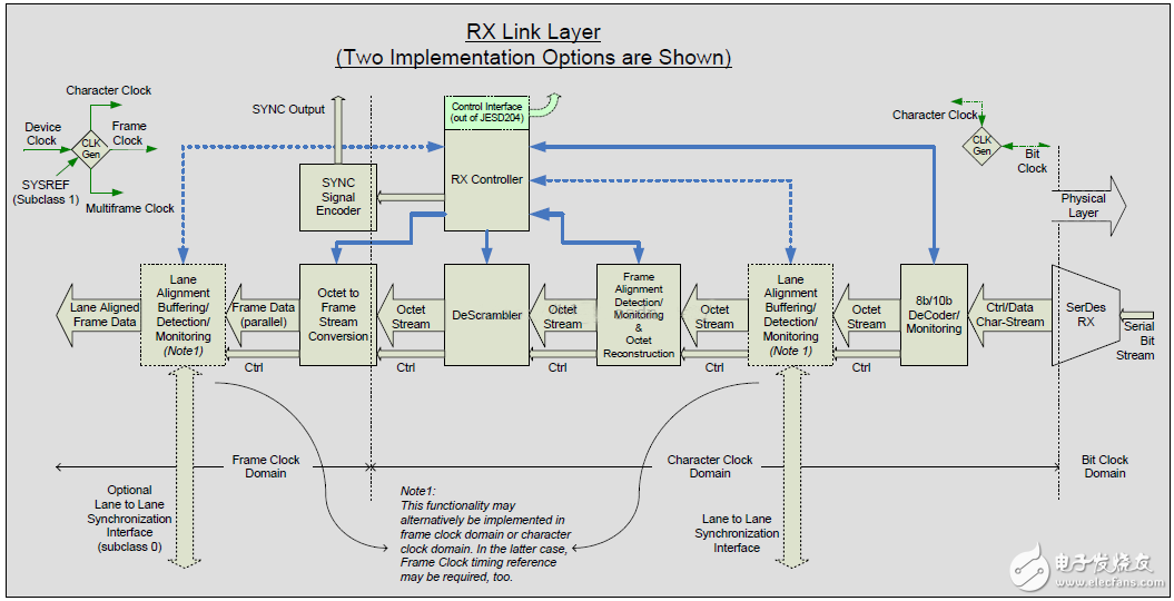
Figure 22: Internal structure of the data link layer receiver
The above is the data link layer control and processing flow in the system. In the SystemC model, each module above will have a corresponding model, and the name of the module in SystemC will remain the same as the module name in the above figure. Consistent.
1.1 RX Controller
Rxcontroller as the control core of the data link, the internal work needs to be completed mainly in two aspects, on the one hand through the data interface and the upper layer for control data exchange, on the one hand to complete the data link layer working state control, this chapter will be the system This section describes the working state control of the data link layer.
The work that needs to be done in the Rx controller includes: code group synchronizaTIon, initial frame synchronization. These two parts are represented by the control of two state machines, which complete the synchronization of data streams and the synchronization of data frames.
1.1.1 code group synchronization
The code group synchronization function completes the synchronization of the data stream when the system is powered on or requires the system to synchronize from the new synchronization. The specific process of the synchronization is implemented in the CDR module of the serdes, and completes the 1-bit data stream to the 10-bit serial conversion. The specific synchronization details are as follows:
After the synchronization request starts, the receiving controller sends a synchronization request, at which time the SYNC signal will remain low, and the transmitter will send a comma code after receiving the synchronization request: /K/=/K28.5/
The receiving controller releases the synchronization request by receiving the following conditions:
Subclass 0 devcies: Releases the synchronization request at the boundary of any data frame after receiving 4 valid K codes.
Subclass 1 and Subclass 2: After receiving 4 valid k codes, the synchronization request is released at the boundary of the mutliframe of the data, that is, the SYNC signal is pulled high.
After receiving the other 4 valid comma codes, the system will consider the data code group synchronization to be completed.
When an invalid data is received, the state machine will enter the detection mode.
If three invalid data are accumulated in the detection mode, the system is considered to be out of sync.
In the detection mode, if 4 correct data is detected, the system synchronization is considered normal.
The synchronization request is transmitted by the receiver to the transmitter via the SYNC signal, and the SYNC is active low. The SYNC signal will only send changes on the rising edge of the frame clock, but there are two cases:
Subclass 0: any rising edge of frame clock
Subclass 1 and Subclass 2: The rising edge of any frame clock and multiframe clock alignment.
The low level duration of the SYNC signal must be greater than the duration of 5 data frames or 9 octets.
P10 Fixed Outdoor
Outdoor Full Color LED Display P10 Fixed installation, which widely used in Outdoor Advertising Projects, like Square, Station, Commercial Center, Street etc. Mainly used for outdoor high density picture display. Outdoor P10 LED Display Screen using the distribution and modular design to improve the stability of the LED Display control system. High Brightness to meets needs of outdoor environment, high gray and high refresh, meet the camera to sheet demand. 3535 table stick package, to meet the large angle of the viewing.
1) 10mm for SMD outdoor LED display, good solution for outdoor LED display installation LED display.
2) 10mm is one of the pixel pitches of usual outdoor LED screens. Therefore, it is a very good solution for rental LED display for both outdoor and indoor use.
3) The module size is 320x160mm, which is of our universal module series. It is convenient for clients to promote it. What is more,users can update their old LED displays made of our universal modules easily.
4) Reasonable PCB design with good heat radiation and achieve long life span.
Salty spray test, high voltage test, varying temperature test, waterproof test, vibration test.Long service time and low attenuation by applying dual channels for heat dissipation.High protection grade of IP65 achieved by patented mask design with waterproof and dustproof fuction.
Looking forward your early response and cooperation!
P10 Fixed Outdoor,P10 Outdoor Led Display,P10 Outdoor Led Display Screen,P10 Outdoor Led Screen
Shenzhen Jongsun Electronic Technology Co., Ltd. , https://www.jongsunled.com