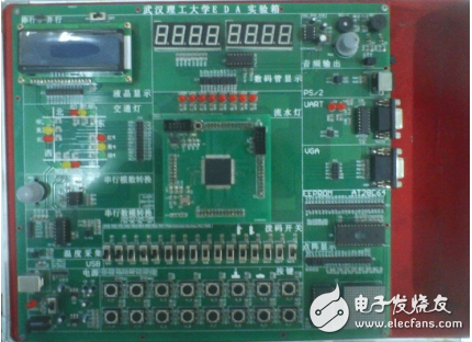
VHDL is a widely used hardware description language that allows designers to write code, simulate and verify its functionality using a simulator, perform logic synthesis and optimization, and finally download the design to programmable logic devices such as FPGAs. This project uses Quartus II software to develop a display system with 8 switches that control 8 digits. When any of the switches (sw0 to sw7) is activated, it displays numbers from 1 to 8 and triggers a sound. Once completed, the design is downloaded to an experiment board to achieve the intended functionality. Quartus II is a comprehensive development environment designed by Altera for their CPLD and FPGA devices. It succeeded Max+plus II, which was previously the main PLD design software. Although Max+plus II is no longer supported, Quartus II has evolved significantly over time, from version 4.0 to 10.0, offering improved features and performance. The software provides a powerful and user-friendly platform for designing and implementing digital systems. Quartus II is known for its ease of use, powerful features, and full integration into the design flow. It supports multiple design entry methods, including schematic capture, VHDL, Verilog, and AHDL. The software includes built-in synthesizers and simulators, making it a complete EDA tool for all stages of design, from input to hardware implementation. It is compatible with various operating systems, including Windows XP, Linux, and Unix. In addition to supporting Tcl scripts, it also offers a graphical user interface, making it easy to navigate and use. Its fast performance, uniform layout, and centralized functions make it ideal for both beginners and experienced users. Quartus II supports a wide range of Altera devices, including MAX 3000A, MAX 7000, MAX 9000, ACEX 1K, APEX 20K, APEX II, FLEX 6000, FLEX 10K, and more. It also supports newer families like MAX II, Cyclone, Cyclone II, Stratix II, and Stratix GX. Additionally, it integrates IP cores such as LPM and MegaFunction modules, allowing users to leverage pre-designed components and reduce design complexity. Quartus II can be used with DSP Builder and MATLAB/Simulink to implement complex DSP applications. It also supports SOPC (System on a Programmable Chip) development, combining embedded software with programmable logic in a single platform. This makes it a versatile tool for system-level design and development. Quartus II provides excellent support for third-party EDA tools, allowing users to integrate familiar tools at every stage of the design process. It is part of Altera’s fourth-generation PLD development platform, which supports collaborative design in workgroup environments and internet-based design workflows. The platform is compatible with tools from major EDA vendors such as Cadence, ExemplarLogic, Mentor Graphics, Synopsys, and Synplicity. Features like LogicLock, FastFit, and advanced debugging capabilities enhance the overall user experience and design efficiency. In traditional hardware design, circuit schematics were the primary design files. However, with the rise of HDLs, designers now primarily use hardware description languages to write source code that describes the behavior and structure of circuits. HDLs, or Hardware Description Languages, allow designers to define the function, signal connections, and timing relationships of a circuit. Many companies developed their own proprietary HDLs, such as Zycad’s ISP, Gateway Design Automation’s Verilog, and Mentor Graphics’ BLM. Among these, Verilog and C-based languages became popular. In 1987, IEEE standardized VHDL (VHSIC Hardware Description Language), developed by the U.S. Department of Defense, as IEEE 1076. Since then, VHDL has gained widespread acceptance in the electronics industry. In 1993, IEEE revised VHDL, introducing a new version (IEEE 1076.1993). Today, both VHDL and Verilog are recognized as industry standards. They are widely used in electronic engineering, from professional designers to university professors and students. VHDL has become the de facto standard for hardware description due to its powerful behavioral modeling and flexibility. (1) VHDL supports top-down design and library-based approaches, enabling the design of synchronous, asynchronous, and FPGA-based circuits. It excels in behavioral modeling, allowing designers to describe large-scale systems without focusing on device-specific details. Most EDA tools can convert behavioral descriptions into RTL representations. (2) VHDL supports the decomposition of large designs and the reuse of existing components. It allows mixing high-level behavioral models with low-level gate-level descriptions, aligning with modern IC design needs. Unlike Verilog, which is closer to gate-level representation, VHDL focuses on functional behavior, making it more efficient for complex designs. (3) VHDL is independent of specific fabrication processes and hardware structures. This means that once a design is verified, it can be mapped to different technologies without significant changes. It is compatible with a wide range of devices, including CPLDs, FPGAs, and gate arrays. (4) VHDL includes generic parameters and subroutine calls, allowing for flexible design modifications. It also provides extensive simulation and library functions, enabling designers to test and validate their designs effectively. (5) As an IEEE standard, VHDL ensures compatibility and reusability across projects and teams. Its strict syntax improves readability and maintainability, making it a preferred choice for engineers worldwide. The hardware platform used in this project is the EDA experiment box from Wuhan University of Technology, as shown in the figure below. The components include LED digital tubes, switches, and a buzzer. The connections between the components are as follows: Data_o[0] PIN_103 key[0] PIN_49 Data_o[1] PIN_100 key[1] PIN_50 Data_o[2] PIN_99 key[2] PIN_51 Data_o[3] PIN_98 key[3] PIN_52 Data_o[4] PIN_97 key[4] PIN_53 Data_o[5] PIN_96 key[5] PIN_54 Data_o[6] PIN_94 key[6] PIN_55 Data_o[7] PIN_91 key[7] PIN_56 l[0] PIN_83 clk PIN_16 l[1] PIN_84 bell PIN_78 l[2] PIN_85 Here, Data_o[0]-Data_o[7] controls the segments of each LED digit, key[0]-key[7] represents the 8 switches, l[0]-l[3] controls the 8-digit display, clk is the clock input, and bell is the buzzer. This setup enables the system to respond to switch inputs and provide visual and auditory feedback accordingly. Connector,Switch Terminal Block,Electrical Components Wenzhou Hesheng Electronic Co., Ltd. , https://www.heshengelec.com