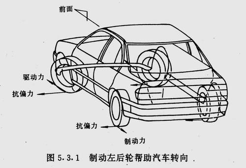
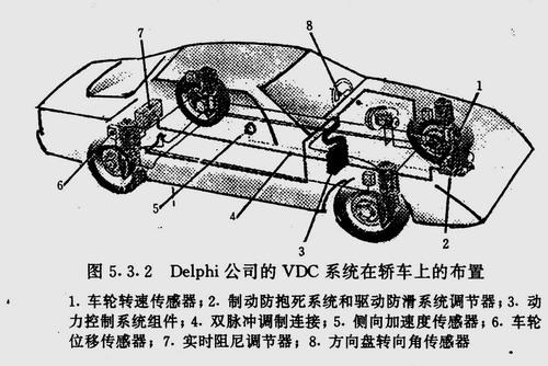
1.ABS/ASR system This article refers to the address: http:// At present, the braking, acceleration and steering of a car are still basic operations that need to be completed by the driver. When the road surface is not well attached or the traffic condition suddenly changes, the driver is required to have skilled driving skills to adapt to changes in driving conditions. The anti-lock braking system described above frees the driver from the high demands of braking. The driving anti-skid control system relieves the driver's high requirements in terms of driving and acceleration. The anti-skid system is a natural extension of the anti-lock braking system function of the car. Its function is to maintain the directional stability of the car while driving, and to make maximum use of the wheel-to-road longitudinal adhesion capability to provide maximum driving force. When the driver over-depresses the throttle on a smooth road surface, the wheel will be excessively slipped. The driving anti-skid device can keep the sliding rate of the wheel in the optimal range by automatically applying partial braking or reducing the power output of the engine. This can prevent the driver from excessively stepping on the negative effect of the accelerator pedal, and obtain better driving safety and good starting acceleration performance. Another advantage is that it reduces wear on the tires and powertrain. Take the driving of a city bus as an example. If the bus stop is on the right side of the icy road surface, the left side is cement or asphalt road, which is a common road condition in the winter in the north. The adhesion on both sides is different and the car is blocked at the start. If the car is equipped with an ASR system, it can balance the speed difference of the drive wheels by braking the wheels. This actually produces a differential lock effect. In this way, on the one hand, the driving force is improved, the adhesion ability of the better-attached side can be exerted to a large extent, and the rapid rotation of the differential planetary gear is prevented, and the early wear of the differential is avoided. This type of control of ASR is called "braking force control". If the two sides of the bus are not attached properly, for example, they are all icy roads. When the accelerator pedal is slammed, the driving wheels on both sides will fly at the same time due to insufficient ground attachment ability. In this case, the drive anti-skid system is controlled by automatically reducing the engine power output. Moderate reduction of engine output power and engine speed can reduce the excessive slip of the drive wheel. On the one hand, it improves the lateral adhesion between the wheel and the road surface, and maintains the directional stability. On the other hand, it increases the longitudinal adhesion ability. Getting started and speeding up. This type of control of the ASR system is called "engine speed control." When the ASR system performs braking force control and engine speed control, the ASR indicator on the instrument panel lights up. In this way, the driver is informed of the condition of the road surface, so that appropriate measures can be taken in time to improve the driving conditions. This control method of the ASR system is called "smooth road condition display control". If a car with a gas suspension is difficult to start or drive on a smooth road surface, the driving force can be increased to some extent by the ASR control function, but it is still not enough for normal driving. In order to increase the driving force and improve the driving condition, the shaft can be passed through the shaft. The method of transferring the load increases the adhesion load of the transaxle and increases the driving force. The axle load transfer is achieved by partially releasing the pressure gas in the transaxle gas suspension, causing the suspension mass to tilt toward the side of the transaxle and the position of the center of mass of the vehicle. The amount of pressure gas released depends on the degree of slippage of the drive wheel. This control method of the ASR system is called "axis load transfer control". In general, the drive slip control includes the above four aspects. It has been successfully applied to these high-end cars, buses and truckers, and has achieved remarkable results. Since the drive anti-skid system is always used in conjunction with an anti-lock system, it is often referred to as an ABS/ASR system. 2. ABS/ASR/VDC system The ABS/ASR system successfully solves the problem of directional stability of the car during braking and driving, but it cannot solve the problem of directional stability when the car is turning. For example, when the car is turning, it is inevitably subjected to lateral and longitudinal forces, and the driver can control the vehicle only when the ground surface can provide sufficient lateral and longitudinal forces. If the ground lateral adhesion ability is relatively low, it will impair the ability of the car to travel in a predetermined direction. When the rainy day car is driving at a high speed, it often slides out laterally, which is because the lateral attachment ability of the ground is insufficient. In order to solve this problem, the developed countries of the automobile industry have recently developed into a vehicle dynamic control system based on the ABS/ASR system (English name is Vehicle Dynamics Control, VDC for short). This system integrates the control system of the main assembly of the car's brake, drive, suspension, steering, engine, etc. functionally and structurally, so that the car can be used under various harsh conditions, such as snow and ice. Good direction stability for different load-bearing, different tire pressures and different degrees of tire wear on upper and lower road surfaces, on curved road surfaces and when driving with evasive movement, braking, acceleration and downhill conditions Sex, showing the best driving performance. The application of VDC completely relieves the driver's high requirements in terms of braking, acceleration and steering, and sets a new milestone in the active and safe driving of the car. The control of steering travel by the VDC system is mainly achieved by means of brake control and engine power output control for each wheel. For example, when the car turns left, if the front wheel tends to slide out of the curve due to insufficient steering ability, the VDC system can detect that the side slip is about to occur, and adopt the method of properly braking the left rear wheel. The braking force generated by the left rear wheel helps the car to turn, allowing the car to continue to follow the ideal route, as shown in Figure 5.3.1. If on the same curve, the rear wheel tends to slide sideways and turn too much, the VDC system adopts the method of properly braking the right front wheel to maintain stable driving of the vehicle. In extreme cases, the VDC system can also reduce the speed of the vehicle by reducing the power output of the engine and reduce the need for lateral adhesion to the ground to maintain stable driving of the vehicle. With the VDC system, the braking distance of the car on the off-road or curved road surface can be further shortened. The VDC system mainly uses the following sensors: Wheel speed sensor for tracking the movement state of each wheel; a steering wheel angle sensor for sensing the corner of the steering wheel; A yaw rate sensor for recording all movement of the car about a vertical axis; a lateral acceleration sensor for detecting the magnitude of centrifugal force during steering travel; Wheel displacement sensor for measuring changes in the relative position of the wheel and body. The heart of these sensors is the yaw rate sensor because the ratio of the yaw rate of the car to the steering wheel angle is an important parameter in response to the steering quality of the car. The signal from the displacement sensor is transmitted to an electronic control unit for controlling the semi-active suspension to improve the grounding performance of the vehicle. Other sensors transmit information about the instantaneous state of motion of the car to the electronic control unit to compare it to the ideal state of motion. Once the car deviates from the ideal route, it takes corrective action in a very short period of time. The corresponding command is issued to the brake control system or the engine control system to maintain the car on the ideal route. Figure 5.3.2 is the layout diagram of the night car of the VIDC system of Delphi. Oval Series Sensor Automatic Dustbin Auto Trash Can,Oval Series Sensor Automatic Dustbi,Oval Series Sensor Dustbin,Oval Series Sensor Office Dustbin NINGBO ZIXING ELECTRONIC CO.,LTD. , https://www.zixingautobin.com