LED lighting is recognized as the next lighting technology due to its power saving, environmental protection and long life, which will replace the existing lighting technology. LED is a cold light source, afraid of heat, 80% of the electrical energy is converted into heat, there must be heat dissipation measures, although LED lighting technology has developed rapidly, there are reports of 200 watts per watt of light, but LED cooling is LED lighting It is a headache, but it has not been solved effectively. It has become a roadblock on the road of universal development of LED lighting.
The biggest problem that hinders the popularization of LED lighting applications is the high price of LED lamps. Although the upstream LED chip manufacturers have divided most of the profits and have a large price reduction space, it is necessary to effectively allocate the entire social resources to the entire industrial chain of LED lighting, effectively reducing Cost, easy for ordinary people to buy and install, LED lighting module standardization is the only way, just like existing lighting (incandescent, fluorescent / energy saving lamps). The obstacle to the standardization of LED lighting modules is the existence of heat dissipation problems.
Heat dissipation is part of heat transfer. Humans have been studying heat transfer for hundreds of years. In the 1960s and 1970s, people were at the peak of heat transfer research. The main driving force was the demand for human aerospace development. At that time, many experts were gathered in the field of heat transfer technology. Many heat transfer researchers became famous people. After that, people's enthusiasm for heat transfer research was gradually reduced. At present, there are very few professionals in heat transfer technology and technology. Heat transfer technology and technology are very mature, just like ripe fruit, falling to the ground and covered by leaves, not being seen by people now, so that when the electronics industry, mainly the CPU in the computer, suddenly increases in heat, People did not pull out the leaves on the ground, pick up the ripe fruit, and transplant the mature heat transfer knowledge into the electronics industry. Instead, it has created a number of new terms: "active cooling", "passive cooling", "heat sinking", etc. It doesn't sound like what it means. English "Sink" is also a very rare term in heat transfer technology and technology.
For the cooling of LED lamps, the current industry lacks clear research results for each heat transfer process in the entire heat transfer process, analyzing: convection (natural) heat transfer from the LED junction to the surface of the air and heat sink, in each process The proportion of heat transfer temperature difference (ie, thermal resistance), which process has the largest temperature difference, that is, the main contradiction, and the factors affecting each heat transfer process, how to reduce the technical direction of its thermal resistance, especially the heat transfer with the largest thermal resistance The process, the technical direction to reduce its thermal resistance is more important. Even with these findings, it must be known to structural engineers because heat transfer is ultimately achieved through structure.
From the perspective of heat transfer technology and technology, LED heat dissipation is not complicated. It only involves a very small part of heat transfer technology - heat conduction heat transfer and convection heat transfer (mainly air natural convection heat transfer), in which heat conduction heat transfer can be utilized. The ready-made heat transfer computer software gets a very accurate solution, such as analyzing the temperature distribution inside the LED package chip (heat transfer process); analyzing the internal temperature distribution from the LED chip to the heat dissipation fin. However, special attention should be paid to the convective heat transfer. When it comes to air flow, it must be studied through a large number of experiments, and computer software calculations have only academic significance and no practical engineering significance. Because the error is too large, there are still many The company is keen to promote such software.
The reasons for the simple problem of LED heat dissipation are: knowledge faults, people with mature heat transfer knowledge are involved in LED heat dissipation research, lack of professional LED heat research institutions, to give clear and correct guiding ideas in the industry, There are so many seminars, but the academic atmosphere is small and the commercial taste is strong. At present, many professional thermal technicians in the industry are transferred from the heat dissipation of computers. Naturally, the commonly used technologies and business activities are brought over. For example, heat pipe technology is widely applied to high-power LED lighting (such as In the streetlights, new business opportunities have been created for heat pipe manufacturers that originally served computer chip coolers. There is even a proposal to use a recirculating heat pipe. If the heat dissipation of the LED lamp uses a general heat pipe like a chicken to kill a pig knife, then the use of a reflux heat pipe is like killing a chicken and lifting the knife. Is there a company in Taiwan that was invented? Liquid immersion cooling technology? The invention of this lack of basic convective heat transfer has also won the Gold Award for the International Invention Exhibition. There are similar enterprises in China, and have a certain popularity, the development of LED liquid cooling technology, said that it has applied for more than 30 patents. These inventors inspired by the car's water tank are not sure why the car's engine uses water (liquid) cooling technology, and the role of water in the heat dissipation process.
This paper proposes a standardization technical solution for implementing LED lighting modules. The heat sink is classified as a component in the luminaire. The wick composed of the LED core and the thermal conductive core will be designed and manufactured into a series of standards, and the cone-shaped thermal core can be effectively solved. The heat conduction between the wick (heat-conducting core) and the heat sink (lamp) enables the wick and the luminaire to be easily disassembled and assembled. The structure is very simple and the cost is low. It is a road to standardization of the module and considers the constant current drive power supply. More reasonable.
Natural convection heat dissipation, no mechanical movement, high reliability, low cost, naturally preferred by LED lights. This paper will explain the principle of natural convection heat dissipation, the maximum heat dissipation and the concept of optimal design. The optimal application structure of the LED lamp heat sink - the sun-type heat sink is proposed. The convection hood is proposed to enhance the heat dissipation by the chimney effect. After a large number of experiments and analysis and research, the results of optimization and strengthening can be achieved, and the level of aluminum for heat dissipation of less than 4 grams per watt can be achieved, and the cost of heat dissipation is significantly reduced. In the future, the cost of heat dissipation will no longer be considered. Not difficult, it will no longer be a problem. (This article does not cover heat transfer within the LED package, which will be addressed and presented in an effective article in a future article.)
Scientific division of modules
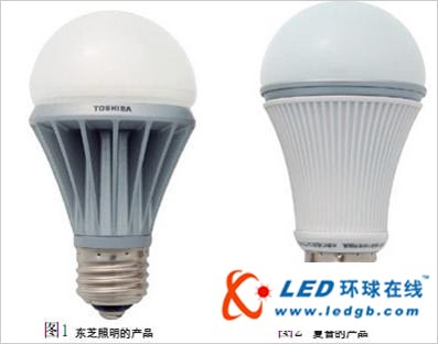
Figures 1 and 2 show the LED lights introduced by Toshiba and Sharp respectively. The LED chips, heat sinks and drive power are integrated into one, and the installation interface is the same as the current incandescent lamp. This structure is very popular on the market, although this design is convenient. Ordinary people install and replace the current incandescent bulbs, but the cost is high, and there is a fatal flaw - the heat is not reliable.
The LED lamps shown in Figures 1 and 2 are placed horizontally, erected or inverted, and the heat dissipation effects are different under the three attitudes. If a lampshade is added, the heat dissipation effect is closely related to the shape and size of the lampshade, if the lampshade is closed. , or the internal and external air flow is poor, the heat dissipation effect will be deteriorated, the light decay will immediately show, or even immediately damage. Therefore, such LED lights will not be the development direction of LED lighting. In addition, the structure of the heat sink itself shown in Figures 1 and 2 is not ideal, and the heat dissipation cost is not low.
Spherical incandescent bulbs, straight tube fluorescent lamps are used because they are easy to manufacture. The accumulation of history made people think of spherical lights and straight tubes as soon as they mentioned the lights. People use lights for the purpose of needing light. LED is a new type of light source, so the design of LED lighting should start from the characteristics of LED light source and establish a new mode.

Figure 3 shows the LED lighting module division proposed in this paper. The heat sink and the driving power source are classified as components in the luminaire. The wick consisting of the LED core, the heat conducting core and the wick cover can be conveniently removed from the heat sink (lamp). Removed and mounted, will be designed into a series of independent standard components.
The electrical connection between the wick and the luminaire is easy, but the thermal connection (heat transfer) between the wick and the heat sink is not that easy. Figure 3 shows an effective and simple solution to this problem: the use of a conical column to contact the heat transfer surface. The cone column and the tapered hole are easy to process, the accuracy is easy to guarantee, and the processing cost is low. The use of a tapered column as a contact heat transfer surface has the significant advantage of ensuring that the contact pressure between the contact faces of the heat conducting core and the heat sink is sufficiently large: as long as a small axial force is obtained, a contact pressure that is amplified several times is obtained, thus the wick The heat transfer resistance between the heat sink and the heat sink is effectively controlled, that is, the heat conduction problem between the two is solved. The following calculation example further illustrates this:
For example, the intermediate diameter of the heat conducting core is 20=20mm, the height h=15mm, and the average gap of the tapered surface of the heat sink is Δ=0.03mm, and the common thermal grease λ=1.0W/m·K, the wick power is Q=12W, Calculate the average temperature difference between the thermal conductive core and the heat sink root:
△t=Q·△/λ·D·л·h=0.38°C, less than 0.4°C
As shown in Fig. 3, the mechanical connection between the wick and the heat sink (lamp) is screwed, and the electrical connection is concentric plug type. The ordinary operator can conveniently install the wick correctly in place without any tools. The structure shown in Fig. 3 is very simple, easy to manufacture and low in cost.
The function of the wick cover in Figure 3: 1, protect the LED core; 2, easy for the operator to install; 3, secondary optics, design and manufacture of different light transmission shades, such as concentrating or astigmatism, to meet different places and applications.
Solved the problem of thermal connection (heat conduction), the universal standardization of the wick is also close to the ruler, and the wicks of different specifications will be divided according to the standard heat dissipation power, such as: 3W, 6W, 10W, 15W, 20W, corresponding to different specifications. The standard interface, unlike the current light bulb (incandescent), is power independent and has only two or three interfaces. Therefore, there are many kinds of standard interface specifications for LED wicks, but the number of types is still limited. The luminaires involved in decoration are in various poses, but the standard heat dissipation must reach the specified value. The luminaires will be divided according to their standard heat dissipation, and their interfaces are standard. The wicking interface of the heat dissipation corresponds. This can be done in design, 10W (standard cooling power) wick can be installed on 12W luminaire, but 12W wick can not be installed on 10W luminaire, which can be achieved through structural differences in the interface. Since each type of lamp has its corresponding fixed installation form, its heat dissipation performance is stable, so there is no need to worry about changing the heat dissipation performance when the user installs, that is, the heat dissipation is stable and reliable.
The module division proposed in this paper makes the heat dissipation resistance of the lamp and the wick and the thermal resistance thermal resistance detection standard and the experimental operation easier. The luminaire can calculate the heat dissipation heat by experimentally measuring the heat dissipation performance curve of the relatively standard thermal conduction core. Resistance; as long as the wick is experimentally determined, the temperature difference between the LED junction temperature and a standard heat sink is calculated, and the thermal resistance of the wick can be calculated. With the heat dissipation of lamps and wicks and the detection standards and operating procedures of thermal resistance, it is easy to quickly identify the advantages and disadvantages of various products. At present, there is no standard and operation for identifying the thermal performance of LED lamps. Instead, the original method is used. For example, street lamps are used for 1000 hours on site. PK is used together with many enterprise products to measure the light decay. It is unscientific and very troublesome. For example, the results measured during the summer and the results during the winter are different, because the temperature in winter and summer changes, and some areas change very much.
According to the module division proposed in this paper and the specific structure of the module, it is easy to formulate a unified mechanical interface standard and electrical connection interface standard of the wick and the heat sink (lamp), and the power supply standard, these standards can also form an international standard. . With these unified standards, luminaire manufacturers will concentrate on designing and manufacturing a variety of luminaires according to different needs; wick manufacturers focus on chip packaging, wick manufacturing, development of fully automatic production equipment, improve production efficiency, reduce costs, and develop The chip package structure with lower thermal resistance inside the package; the chip manufacturers concentrate on the development and production of the chip, and more investment in how to reduce the cost and improve the photoelectric efficiency; the power supply manufacturer concentrates on the development of the power supply, the dedicated driver chip, improves the power efficiency, and reduces the product. cost. In the LED lighting industry chain, the manufacturers at all levels have clear division of labor, close cooperation, and independence, and build a perfect modern industrial company. Social resources will be rationally allocated to each chain, and the cost price will be significantly reduced. The popularity of LED lighting is nearing the eye.
In short, this paper proposes the scientific division of the module of LED lighting: 1 heat dissipation is stable and reliable; 2 easy to realize the standardization of the module of LED lighting, and the corresponding testing standards and operating procedures, improve the entire industrial chain and reduce the cost.
About the power supply standard:
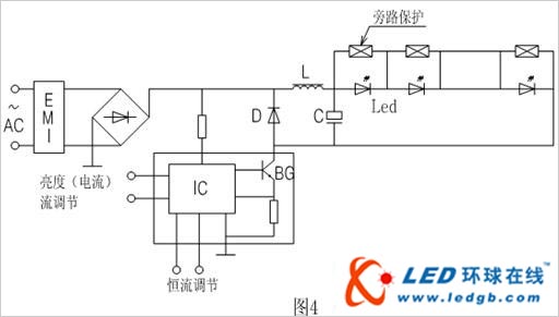
This paper believes that constant current drive should be used. The LED chips in the wick are connected in series (partially connected in parallel). As shown in Figure 4, each LED chip (or parallel group) is provided with a bypass protection component. The LED chip is damaged and becomes disconnected. Because the voltage is too high (such as twice the maximum voltage of the LED), the component breaks down and forms a permanent short circuit, so that no damage is caused by one or two LED chips. The wick is scrapped. For example, a 12W LED lamp has a total of 12 LED chips. If there are two damages and the brightness is reduced, the current adjustment terminal can be used to adjust the current and compensate for the reduced brightness, so the reliability of the lamp is high.
The advantages of using a constant current drive power supply are as follows:
1. It is easier to realize a unified standard power supply. For example, a standard uniform constant current is set to 350 mA.15W wick, and the rated voltage is 43V. The rated current of the chip is related to the chip area in the LED chip, so it is easy to adjust the design. A wafer that satisfies the unified rated current standard, and can also be connected in parallel by a local chip, such as two or three LED chips in parallel to achieve a uniform rated current (such as 350 mA);
Second, the drive circuit is simple, the components are small, the cost is low, and the power supply efficiency is high. Due to the low operating current (350 mA), the switching loss of the switching power tube BG is small, the power supply efficiency is high; using the standard standard constant current (350 mA), the switching power tube BG can be integrated into the driving IC (as shown in Fig. 4). The dotted line shows) and the rated power range is large, working from 1W to 70W (the mains is AC220V). The larger the output power (the more the LED core is connected in series), the higher the output voltage of the power supply, so the smaller the switching voltage of the switching power tube BG, the smaller the switching loss, and the higher the efficiency of the power supply.
Third, the principle and optimization of natural convection heat dissipation
The heat dissipation process is ultimately the transfer of heat into the air, which is carried away by the air flow (convection), and the radiative heat transfer of the heat sink is very low, so it is not considered. Heat taken away by air flow (ie heat dissipation) Q:
Q=Cp ·M· (T2-T1) (1)
Cp - the specific heat of the air, is a fixed value.
M--air flow.
(T2-T1)--The temperature difference between the air temperature T2 at the outlet of the heat sink and the air temperature T1 at the inlet. The air temperature T2 at the outlet does not exceed the wall temperature Tw of the heat sink, that is, (T2-T1) has the largest possible value.
It can be analyzed from formula (1) that the most effective way to increase the amount of heat dissipation is to increase the air flow.
In the natural convection heat transfer process, the driving force of the air flow is: the buoyancy F generated by the air being heated by the temperature and the specific gravity is decreased:
F=∫V g(Ïo- Ïa )dv=∫V gÏo(1- ) dv (2)
G--gravity acceleration.
Ρ--air density.
V--The volume of the radiator.
TO-- Ambient atmospheric temperature.
Ta--The air temperature inside the radiator.
Air flows through the heat sink, the resistance generated by the heat sink? :
?= ∫S α · g · Ï Â· u2 · ds (3)
S--The surface area through which the air flows, that is, the heat dissipation area of ​​the heat sink.
The α--flow resistance coefficient is closely related to the structure of the heat sink and the form of air flow.
u--The flow velocity of air in the heat sink. The higher the flow rate u, the larger the air flow rate.
The heat dissipation amount Q of the heat sink should also satisfy the following formula:
Q=∫S h (Tw-Ta) ds (4)
H--convection heat transfer coefficient.
(Tw-Ta) - The difference between the heat sink wall surface temperature Tw and the air temperature Ta in the heat sink, and the heat sink temperature Tw is limited by the LED chip junction temperature.
The above four formulas constrain the natural convection heat dissipation process, and the buoyancy F should be equal to the flow resistance? Add air momentum increase (Ï2) (explained in more detail in the next section). Reduce flow resistance? , means that the air flow rate u2 increases (ie, the flow rate M increases), and the buoyancy F demand decreases. It can be seen from the formula (1) that the increase of the flow rate M is beneficial to the increase of the heat dissipation amount Q, and the buoyancy F requirement is decreased. From the formula (2), it can be analyzed that the air temperature Ta in the heat sink can be lowered, and the formula is 4) It can be seen that the favorable heat dissipation amount Q is improved, which means that the flow resistance is lowered, and in all respects, it is advantageous for the heat dissipation amount Q to be improved.

Reducing the flow resistance coefficient α can effectively reduce the flow resistance. When the fins of the heat sink are erected up and down, the air directly enters the heat radiating fins from bottom to top, and the low temperature air directly enters the heat radiating fins. The formula (4) is favorable for convective heat transfer; the flow direction of the air is consistent with the buoyancy direction. The resistance is the smallest. Therefore, the heat sink should be designed to be vertically connected to prevent the air from flowing and eddy current. According to formula (3), the flow resistance is proportional to the square of the flow velocity of the air in the fin, and thus reducing the flow rate can effectively reduce the flow resistance. Increasing the flow area of ​​the air in the fins can reduce the air flow rate M and reduce the flow rate. The solar fancy structure heat sink, as shown in Figure 5, the LED chip will be concentrated on the central heat conduction column section, not only the heat source (LED chip) discrete hot rib root distance is close, the thermal conductivity inside the heat conduction column is small, and the LED The chip is concentrated, and the occupied cross-sectional area is small, that is, the effective circulation area of ​​the air is large, thereby facilitating the reduction of the flow resistance. This shows that the heat sink of the solar fancy structure is the best structure for the heat dissipation of the LED lamp. From the aspect of manufacturing, the aluminum extrusion process is used to manufacture the sunflower aluminum profile, and then the cutting becomes a heat sink, which can produce heat sinks of various shapes, with high production efficiency, few processes, and low cost.
It is analyzed by formula (2): If the volume V of the radiator is constant, the space occupied by the radiator is fixed, and the air temperature Ta in the radiator is increased, which is beneficial to increase the buoyancy F, but it is not favorable for the heat dissipation rib from the formula (4). Convective heat transfer (ie heat dissipation) between the sheet and the air. From the analysis in formula (4), by increasing the number of fins (ie, the rib density) to increase the heat dissipation area S, it is beneficial to increase the heat dissipation, but from the analysis of equation (3), the flow resistance is correspondingly increased. .
The above analysis shows that in the natural convection heat transfer, by increasing the heat dissipation fin density (reducing the gap between the ribs) to increase the heat dissipation area, the purpose of heat dissipation is increased, but there are opposite and contradictory factors. The heat dissipation is limited, and it is even possible to get the opposite result of reducing heat dissipation. It can be concluded that when the space occupied by the heat sink is constant, there is a maximum natural convection heat dissipation, which corresponds to the optimum rib structure (rib density), and the maximum heat dissipation is proportional to the flow cross section of the heat sink. . The author has confirmed this conclusion through a large number of experiments, and summed up the empirical formula for calculating the optimal rib density, and can calculate the optimized LED lamp heat sink.
Fourth, the natural convection heat enhancement enhancement
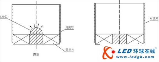
A convection cover is arranged above the heat sink. As shown in FIGS. 6 and 7, the suction flow principle of the chimney is used to increase the flow rate of air flowing through the heat sink to achieve an enhanced heat dissipation.
The suction force (ie buoyancy) generated by the convection hood can be analyzed by theoretical calculation. As shown in Fig. 8, the control volume method is used for analysis. According to the principle of controlling the momentum balance in the body, it can be deduced:
F=∫V gÏo(1- ) dv =Ï2 B +Æ’ (5)

This description: The suction force increases the momentum of the air (Ï2) while overcoming the flow resistance? The increase in air momentum means that the air flow rate is increased, which is obtained by the formula (1), and the heat dissipation amount is improved. The suction force is proportional to the volume V in the convection hood, which increases the temperature of the air in the convection hood and helps to increase the suction force. Further analysis can also be concluded that to have a high suction force, the heat sink should be placed at the lowest end of the convection hood as much as possible, and the heat sink should be tight.
According to the above conclusion, the suction force of the convection hood is proportional to the volume V in the convection hood, so that in some cases, for example, due to the decorative needs, the height dimension of the luminaire is limited, and the size of the cross-sectional area can be increased. The same volume, the same suction power. In the product design, you can make full use of the lampshade on the luminaire as a convection hood, which has both decorative effects and enhanced heat dissipation.
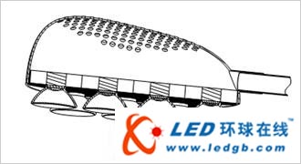
For downlights, the lamp is naturally designed as a convection hood. The LED street lamp shown in Fig. 9 has 10 hexagonal sun-shaped fins, which are assembled by a honeycomb structure, and are provided with a large-sized rear shell. The rear shell is provided with a vent hole, and the rear shell is formed. The convection hood.
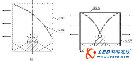
When the convection hood is erected, the suction of the convection hood is most effective. The heat sink is in the form of a sun flower, and the LED core can only face upward or downward, as shown in Figs. To solve the problem of flat lighting, the LED lamp shown in Figures 10 and 11 can be used. The convection cover is made of transparent material. At this time, the convection cover is the lamp cover, the LED core is facing upward, and the convection cover is provided with a mirror, which is emitted from the LED core. The upward light is reflected by the mirror into a flat shot. If the reflection angle of the mirror is adjustable, the flat angle of the light can be adjusted. For tunnel lights, or similar lighting, the structure shown in Figures 10 and 11 can be used.
V. Analysis and comparison of experimental results
Figure 12 is a photograph of a heat sink of a 20W LED downlight in a factory. What is the diameter of the shape? 86mm, height 65mm, is a heat sink profile made by aluminum extrusion process, completed by a variety of mechanical processing steps, net weight 250 grams, heat sink surface S is 0.1m2. The experimental curve B in Figure 13 is the heat dissipation of the heat sink Characteristic experiment results, the ordinate Q is the heat dissipation power, the unit is W, the experiment uses the heating sheet to heat, and the heat is read from the electric power meter; the abscissa ΔT is the temperature Tw of the heat conducting plate on the heat sink (attached to the aluminum substrate) (set with The difference between the 5 electric thermocouples and the ambient air temperature TO. Curve C in Fig. 13 is an experimental result of the mesh cover with the punched holes added to the heat sink. What is the specification of the mesh? 6mm (aperture) × 2mm (hole clearance), adding a net cover, increasing the flow resistance of the air, so the heat dissipation performance is significantly reduced.
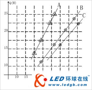
The experimental curve A in Fig. 13 is the experimental curve of the heat dissipation characteristics of the heat sink designed by the patented technology. The solar fancy aluminum heat sink is used, and the structural size is optimized and calculated. The convection hood with a height of 120 mm is adopted, and the outer diameter of the heat sink is ? 88mm, weighs 80 grams. Compared with curve B, you can see that when? When T(Tw-To) is 30 °C, the heat dissipation of the heat sink designed by this patent technology is 1.5 times that of the product shown. It can be calculated that the surface convection heat transfer coefficient h is doubled and converted into watts per watt. The aluminum material for heat dissipation is 3.6 g/W. If the actual heat output of the LED lamp is 17.5W, the heat sink designed by this patent technology can reduce the temperature by as much as 10 °C. The cost of the heat sink designed by this patent technology is also 2 yuan multi-point (calculated according to 25 yuan / Kg extruded aluminum profiles), and the current product shown, adding 30% of the cutting consumption, and cumbersome mechanical cutting process The production efficiency is very low, and the cost should reach nearly 20 yuan/piece.

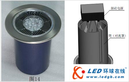
Table 1 lists the heat dissipation characteristics of the current lighting condition of the 20W downlight. Compared with the patented technical sample, Figure 14 is a photograph of the technical sample of the patent, and Figure 15 is a technical design of the patent. The LED chip used is Cree. Xlamp XP-E, the current product uses 10, the patent improvement is also used 10, the patent is improved by 9 and both are connected in series.
Total Power - Data measured using a power meter, including the loss of the drive power.
The Tw--Led chip is soldered to the temperature of the aluminum substrate. The current product uses six thermocouples and is attached to the average temperature of the surface of the aluminum substrate. This patent is improved by using two thermocouples on the side of the aluminum substrate. A hole with a diameter of Φ1.2 mm and a depth of 4 mm was drilled, and the average temperature of the two thermocouples inserted into the hole was measured.

It can be seen from Table 1 that the temperature of the LED lamp product designed by the patented technology is reduced by 9 °C.
Figure 16 (a) is a LED downlight that is now called 60W in a factory. What is the outer diameter? 185mm, height is 130mm, the heat sink is made of heat pipe ribbed structure, and Figure 16 (b) shows the internal structure of the punched mesh cover. The heat dissipation characteristic curves F and E in Fig. 17 are the experimental results of the heat sink with a net cover and a meshless cover, respectively, and the two curves are compared, and it can be seen that the influence of the mesh cover on the heat dissipation is obvious. The curve D in Fig. 17 is a heat dissipation characteristic curve of the heat sink designed and optimized by the patented technology. It is assembled by 7 hexagonal sun-shaped fins, and the maximum outer diameter is? 185mm, convection cover height is 120mm. Compared with the current product (curve F), the heat dissipation is significantly improved when the temperature difference? When T(Tw-To) is 25 °C, the heat dissipation is increased by 50%. The current product (as shown in Figure 16(b)) uses a heat pipe, which has a complicated structure, many production processes and low production efficiency. The cost of the product is more than 100 yuan. / pieces. The radiator designed in this patent, the weight of aluminum is 285 grams, calculated at 25 yuan / Kg, which is 7.5 yuan / piece, less than one tenth of the product shown in Figure 14.

The above experimental results and analysis and comparison show that the LED lamp heat sink technical solution proposed in this patent adopts the sun-type heat sink, and the optimized heat treatment cost is significantly reduced. It can be said that the heat dissipation of the LED lamp will not be a problem, and it is no longer necessary to consider it. Cooling costs.
ALPS TACT Switch
Alps Tact Switch,Navigation Use Switch,Square Thin Surface Switch,Surface Mount Push Button Switch
DA CHENG MINGHUA LIMITED , https://www.alpsswitch.com