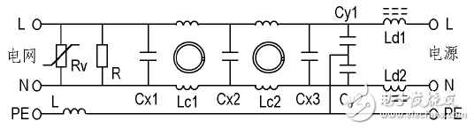
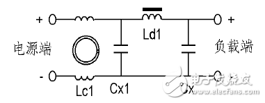
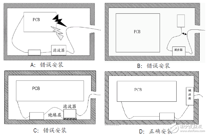
1. Overview 1.1 When do you need electromagnetic compatibility rectification and countermeasures? For an electronic or electrical product, its electromagnetic compatibility should be considered at the design stage, which reduces the possibility of electromagnetic compatibility problems in the production phase to a lower level. However, whether it meets the requirements, the compliance of the electromagnetic compatibility standard is finally verified by the electromagnetic compatibility test. Due to the complexity of electromagnetic compatibility, even if a product with a comprehensive consideration of electromagnetic compatibility design is considered, in the design and manufacturing process, some electromagnetic interference factors will inevitably occur, resulting in the final electromagnetic compatibility test being unqualified. In electromagnetic compatibility testing, this situation is still relatively common. Of course, we can completely follow the normal electromagnetic compatibility design idea and follow the electromagnetic compatibility design method and system method to redesign the electromagnetic compatibility problem of the product. Solve the existing electromagnetic compatibility hazards from the source. This is in the field of electromagnetic compatibility design. At present, domestic electronic and electrical products are more common: when the product is in electromagnetic compatibility type test, the product design has been finalized, the product casing has been opened, the PCB board has been designed and produced, the component board has been processed, and even the product has been produced. Come out and wait for the shipment to release. For the electromagnetic compatibility problems of such products, only the problem solving method of "what problems occur and what problems are solved" can be adopted to minimize the modification of the products to meet the electromagnetic compatibility requirements. This is the scope of electromagnetic compatibility rectification measures, which is the problem we need to explore in this course. 1.2 Common electromagnetic compatibility rectification measures For common electromagnetic compatibility problems, we can solve most of the problems by comprehensively adopting the following rectification measures: you can apply conductive adhesive on the mounting surface of the shield, or add conductive pads at the assembly surface, or even Remedy with conductive metal tape. The conductive gasket may be a braided metal wire, a soft metal (copper, lead, etc.) having a lower hardness and being easily molded, a rubber covering the metal layer, a conductive rubber or a comb-like reed contact finger. Under the premise of not affecting the performance, properly adjust the cable orientation and arrangement of the equipment so that different types of cables are isolated from each other. Change the ordinary small-signal or high-frequency signal cable to a shielded cable, and change the ordinary high-current signal or data transmission signal cable to a symmetric stranded cable. Strengthen the mechanical properties of the grounding and reduce the grounding resistance. At the same time, there must be a separate low impedance grounding for the device as a whole. Add or connect a line filter to the device power input line. When possible, shield and isolate important devices, such as adding a well-grounded metal isolation plate or a small shield. Connect a small capacitor in parallel with the power supply input of each device to bypass the high frequency interference caused by the power supply. Below, we separately issue problems and solutions and remedial measures in the test of electromagnetic compatibility test items such as conducted emission, radiation emission, harmonic current, electrostatic discharge, electric fast pulse, and surge of electronic and electrical products. Let's discuss together. According to the characteristics of each project, we divide these contents into three categories for discussion: Electromagnetic disturbance emission class: conducted emission, radiation emission Harmonic current class Transient impulse immunity class: electrostatic discharge, electrical fast pulse, surge shock 2. Electromagnetic disturbance emission test common problem countermeasures and corrective measures For the electromagnetic emission test countermeasures and rectification, we will discuss the AV and IT products in detail in the next topic "Electromagnetic Compatibility Problems and Countermeasures in Electronic Products 3C Certification Testing". Here, only some outline introductions will be made. Further discussion. 2.1 Main sources of electromagnetic disturbance in electronic and electrical products The switching circuit of the switching power supply of the equipment: the disturbance source has a frequency of several tens of kHz to more than one hundred kHz, and the higher harmonics can be extended to several tens of MHz. The rectification loop of the DC power supply of the equipment: the upper limit of the frequency of the power frequency rectification noise can be extended to hundreds of kHz; the upper limit of the frequency of the high frequency rectification noise can be extended to several tens of MHz. Brush noise for DC motors in electric equipment: The upper limit of the noise frequency can be extended to hundreds of MHz. Operating noise of AC motors for electric equipment: Higher harmonics can be extended to tens of MHz. Harassment emission of variable frequency speed control circuit: the frequency of disturbance source is from tens of kHz to several tens of MHz Switching noise for device operating state switching: The upper limit of the noise frequency can be extended to hundreds of MHz. Electromagnetic disturbance of crystal and digital circuits of intelligent control equipment: The disturbance source has a frequency of several tens of kHz to several tens of MHz, and the higher harmonics can be extended to hundreds of MHz. Microwave leakage from microwave equipment: The main frequency of the disturbance source is GHz. Electromagnetic disturbance emission of electromagnetic induction heating equipment: the disturbance source has a frequency of several tens of kHz, and the higher harmonics can be extended to several tens of MHz. The local oscillator and its harmonics of the high-frequency tuning loop of the TV electroacoustic receiving device: the main frequency of the disturbance source is from 10 MHz to several hundred MHz, and the higher harmonics can be extended to several GHz. Digital processing circuits for information technology equipment and various types of automatic control equipment: the frequency of the disturbance source is several tens of MHz to several hundred MHz, and the higher harmonics can be extended to several GHz. 2.2 Disturbance source location 2.2.1 Positioning according to the measurement curve: Basis: Excessive disturbance frequency range, excessive frequency disturbance distribution, narrowband disturbance or broadband disturbance According to the working mode and internal structure of the device under test: Is there a half-wave rectification and symmetrical/asymmetric power supply adjustment circuit that is not recommended by the standard? Is the layout of the circuit board in the internal structure reasonable? Is the internal cable routing reasonable? Is the internal filter (filter circuit) installed properly? Is the internal circuit grounding and bonding method reasonable? Does the chassis shield meet the requirements of the corresponding product? 2.2.2 According to the composition and function of the device under test: Is there a secondary power supply inside the device, how does it work? Is there a drive motor in the device, the type of motor? Is there a variable frequency speed control circuit in the equipment? Is there a digital control or intelligent control circuit in the device? Do you use a crystal oscillator? Is there a programmed relay or switch circuit in the device? Does the equipment work with electromagnetic waves or microwaves? Is there a working wireless transceiver circuit in the device? 2.2.3 Fault location based on the function of the function module: If the various modules of the device can suspend and resume work, the source of the harassment can be determined by suspending the work of these modules one by one. If the module can not independently suspend and resume work, it can be suspended and resumed by combining with other functional modules of the device to determine the approximate source of the harassment. If the module can not independently suspend and resume work, it can be judged by the combination of the qualified function modules of other devices to determine the source of the harassment. For modules suspected of exceeding harassment, the harassment decision can be made by means of permutation. 2.3 Problems and countermeasures for continuous conduction and emission of electronic and electrical products The continuous measurement of the continuous conduction disturbance of household appliances is measured at a frequency range of 148.5 kHz to 30 MHz (actually 150 kHz to 30 MHz). Measurements are made on the power supply terminals and load terminals and additional terminals. The main source of continuous conduction disturbance: Switching frequency and harmonic disturbance of switching power supply, rectification noise of power rectifier circuit, The operating noise of the AC motor, the brush noise of the DC motor, Electromagnetic disturbance of electromagnetic induction heating equipment, Crystal oscillator and digital circuit electromagnetic disturbance of intelligent control equipment When we find the source of harassment beyond the punctuation through harassment targeting, The corresponding disturbance suppression measures can be adopted. (Explanation of fault location and source of conducted disturbance) Continuous conduction disturbance to the general power supply terminal can be suppressed by the following circuits: Figure 1: AC power filter network Conducted disturbances to the load and additional terminals can be suppressed by the following circuits Figure 2: DC Output Filter Network Regardless of the suppression of the power terminals, load terminals and additional terminals, if you use a separate filter, you need to pay attention to the installation method. Figure 3: Filter installation method
KNB1-32 Mini Circuit breakers, also named as the air switch which have a short for arc extinguishing device. It is a switch role, and also is a automatic protection of low-voltage electrical distribution. Its role is equivalent to the combination of switch. Fuse. Thermal Relay and other electrical components. It mainly used for short circuit and overload protection. Generally, According to the poles, Mini Circuit Breaker can be divided into 1P , 1P+N , 2P, 3P and 4P.
KNB1-32 Miniature Circuit Breaker KNB1-32 Miniature Circuit Breaker,KNB1-32 Electronics Miniature Circuits Breaker,KNB1-32 Automatic Miniature Circuit Breaker,KNB1-32 Mini Circuit Breaker Wenzhou Korlen Electric Appliances Co., Ltd. , https://www.korlen-electric.com