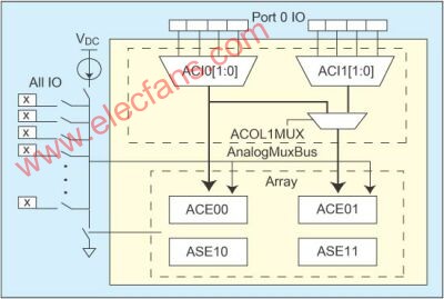
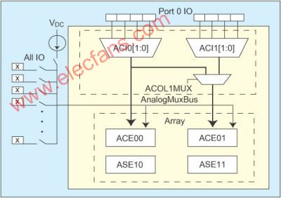
Cypress's CY8C21&TImes;34 Programmable System-on-Chip (PSoC) mixed-signal array features an I/O analog multiplexer that uses a single SoC since each pin can be used as an analog input Control applications that require a large number of different types of sensors can be easily implemented. This article describes how to use the device to simplify design in a variety of sensor control applications. Figure 1: Analog multiplexer/system connection. Industrial control applications often require many analog inputs, and even the simplest fan controller with one PWM output may require monitoring of a large number of temperature sensors. Analog input is a valuable resource that is often consumed quickly. In many cases, design engineers have to resort to a more expensive component, resulting in some extra idle resources, or an external multiplexer must be added to meet the increased need for analog input signal access. Moreover, sensors do not always provide a buffered output voltage, and they have the potential to convert signals to certain non-voltage parameters, such as resistors or capacitors. In many cases, the cost of signal conditioning can exceed the cost of the controller. When choosing a controller, there is always the problem that the design engineer must specify how many analog inputs. For a system that only requires 6 inputs, is 8 inputs sufficient? Will the demand continue to increase? How many analog inputs can a particular controller series handle? If my design needs to be upgraded to one with more inputs The device, then what is my alternative? This choice must be made while trying to meet the cost requirements of the project while complying with the changing specifications of the customer and the marketing department. A simple solution is to make each pin an analog input that was not possible in the past, and the I/O analog multiplexer turned it into reality. The I/O analog multiplexer is a large crossbar switch that allows any pin to be connected to an analog array of a control system. It is such a multiplexer built into the CY8C21x34 configurable mixed-signal array. The device has a switch on each pin, and when a switch is selected, it is connected to an analog bus. The controller family offers up to 28 I/O pins, each of which can be an analog input. The bus is also connected to an analog array. The analog array consists of four configurable modules that, when combined with digital resources, form a complex signal processor. Possible analog functions include a 10-bit analog-to-digital converter (ADC) and a comparator. Figure 2: Analog multiplexer with current DAC. A sensor is a transducer that transforms a physical quantity into a parameter that can be electrically measured. For many transducers, the end result of this conversion is voltage. For example, the LM35 temperature sensor provides an output voltage proportional to temperature. The temperature measurement only needs to digitize the output voltage, and the voltage can be converted to temperature by using an appropriate conversion formula (Temp=Vmeasured/10mV in this example). As an example of a control application that requires measuring 16 temperatures in the system, it is simple to place the sensors where they are needed and connect them to a single pin. The analog array is configured as an ADC and connected to the analog bus. With this topology, each sensor can be sequentially connected to an analog bus and digitized. Some types of sensors have a resistive output, and these sensors include thermistors, photocells, strain gauges, and conduction units. The information readout of these sensors needs to be done by resistance measurement. The usual practice is to use a DC current to simulate the sensor output and measure the load voltage. To facilitate the measurement of the resistance, a programmable current DAC is added to the analog bus of the CY8C21x34. The current DAC can be selected and adjusted in two ranges: 0-20μA or 0-400μA. To read the resistor, simply connect the sensor to a pin connected to the analog bus and turn on the current DAC, which will produce a load voltage equal to the product of the resistor and current. This voltage can be read out using an analog module configured as an ADC. One way to calibrate this design is to sacrifice a pin to connect an external reference resistor. First measure the reference resistance, the measured voltage is always proportional to the resistance; then measure the sensor resistance, the sensor resistance can be calculated with the known measured voltage and the resistance of the reference resistor: The accuracy of the sensor resistance reading is now limited only by the accuracy of the reference resistor and the resolution of the ADC. Any gain error will not be brought into the calculation. Then, assuming that there is a change in the specification of the previously discussed control application, a thermistor is required instead of the LM35. The particular thermistor selected has a nominal resistance of 10 kW / 25 ° C. A simple implementation is to place the thermistors in the desired locations and connect them to a single pin. Connect an extra pin to the 10kW reference resistor and set the current DAC to generate a current of 100μA. By configuring the analog array as an ADC, each load voltage can be measured sequentially and the resistance of all thermistors calculated, and the appropriate values ​​are used to convert these resistance values ​​into temperature values. Figure 3: Analog multiplexer with discharge circuit. Some types of sensors have capacitive outputs, including accelerometers and pressure sensors. Unlike a resistive sensor that produces a DC load voltage, when excited by a DC current, the capacitive sensor produces a ramp voltage that is proportional to the excitation current and inversely proportional to the measured capacitance. In order to facilitate the measurement of the slew rate, a discharge switch is added to the analog bus of the CY8C21x34. When selected, the switch will discharge the analog bus to ground. A variety of configurable resources can be employed to control its operation. To measure the slope, configure the analog module as a sample comparator. The output of the comparator is responsible for controlling the discharge switch. This topology forms a relaxaTIon oscillator. When the ramp voltage rises to the trip point, the comparator closes the discharge path and re-discharges the analog bus to ground. Then, the comparator releases the switch and the voltage continues to rise. The comparator output is fed to a digital portion configured with a frequency counter or a period timer. The capacitance value can be derived from the measured digital signal. Now, suppose a control application that needs to measure pressure. The development of micromachining technology has enabled the fabrication of inexpensive pressure sensors using silicon films that are mounted on glass substrates. A change in pressure causes the film to shift, resulting in a change in capacitance. However, thermal expansion also causes changes in capacitance, making these sensors susceptible to temperature. A corresponding solution is to place a reference capacitor on the same substrate and measure the ratio of the two capacitors. When measuring pressure, connect both capacitive outputs to the PSoC pin. The analog section is now configured as a sample comparator with a 1.3V trigger level and is used to control the discharge switch. The current source was set to 10 μA. For a 10pF nominal capacitance, the resulting voltage change slope is 1V/μs. At this rate, the ramp voltage will take 1300 ns to reach the 1.3V trip point. The frequency calculated by the digital part is 769 kHz. The measurement frequency is inversely proportional to the measured capacitance. Perform a sequential measurement of each capacitor and calculate a ratio. The ratio of these two values ​​will eliminate any errors caused by current sources or inaccuracies in the system clock used to calculate the frequency.
Bluetooth Headphone/Noise Cancelling Bluetooth Headphones/Wireless Bluetooth Headphones
Items introduction:
We are works on Wireless Bluetooth Headphones/Noise Cancelling bluetooth headphones
1: Function:Bluetooth, Microphone,Noise Reduction
2: Feature: High quality with 1 pcs of bluetooth headphone, 1 charging cable
3:Use for :PC / mobile Phone /listening music and suit for Bluetooth device
Its can attractive to purchase and use for the customer.
Items as below:
Bluetooth Headphones Bluetooth Headphones,Anc Bluetooth Headset,Bluetooth Headset,Bluetooth Earphones Shenzhen Greater Industry Co., Ltd. , http://www.szgreater.net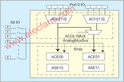
![]()