Air Filter: Prevents harmful debris, dirt and
contaminants from entering your engine.
Engine protection is the name of the
game.So is engine performance. Acceleration can improve up to after an old,
dirty air filter is replaced. Our Pennzoil air filters are engineered to trap
harmful contaminants that can damage your engine.
Old and dirty air filters lead to
reduced engine power, decreased throttle response, weaker acceleration and
increased engine wear. Sounds ugly. Well, it is, and you should have it
replaced when it gets bad.
Air Filter Air Filter,Car Air Filter,Indoor Air Filter,Car Cabin Air Filter Donguan Bronco Filter Co., Ltd , https://www.broncofilter-cn.com
Overview The MAXQ microcontroller development platform is supported by Rowley Associates' CrossWorks programming tool. This application note explains how to use CrossWorks v.1.0 and the MAXQ2000 evaluation board to create, build, and debug C applications for the MAXQ platform. These instructions will still apply to future versions of CrossWorks. The characteristics of the MAXQ2000 microcontroller will be described in the "Settings" section below. Before setting up the MAXQ2000 evaluation board to write code, you must first connect the MAXQ2000 evaluation board.
The evaluation board includes three circuit boards, one of which has a small LCD screen. Figure 1 shows the largest circuit board connected to the LCD daughter board. This is the actual MAXQ2000 evaluation board, which we will discuss later. Connect the LCD to the connector labeled J3 on the MAXQ2000 evaluation board (see Figure 1). 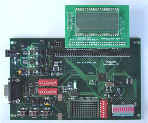
Figure 1. The MAXQ2000 evaluation board with the LCD board installed
The MAXQ2000 loader and debug engine use the JTAG protocol for communication. Because there is actually no commercial, universal JTAG adapter for personal computers, Dallas Semiconductor provides a serial-JTAG conversion circuit board, the third circuit board. Connect the connector labeled J4 on the MAXQ2000 evaluation board to the connector labeled P2 on the JTAG board using the small 10-core cable provided with the evaluation board. See Figure 2. Note that the red side of the connector corresponds to pins 1 and 2 on both boards. 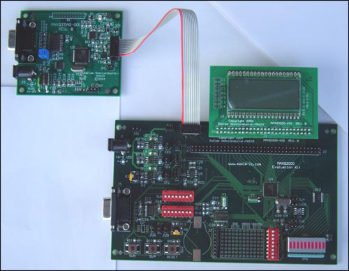
Figure 2. MAXQ2000 evaluation board and JTAG board connection
There should be 3 jumpers on the MAXQ2000 evaluation board. Pins 1 and 2 of connector JU1 should be connected using jumpers. Similarly, pins 1 and 2 of JU2 and pins 1 and 2 of JU3 should also be connected using jumpers. In addition, make sure that the high-frequency crystal is mounted on Y1 (near the microcontroller on the circuit board). The demo code in this application note assumes a 16MHz crystal oscillator, which is installed on the evaluation board. The JTAG board should also have three jumpers installed on the JH1, JH2, and JH3 connectors.
This setting also requires a positive 5V ± 5% DC power supply. For more information about power requirements, please refer to the MAXQ2000 evaluation board documentation. Connect the power supply to the power socket J2 of the JTAG board.
Finally, connect the PC serial port to the JTAG board. Use a conventional 9-core straight-through serial cable to connect a serial port of the computer to the serial port of the JTAG board. Note: Do not connect to the serial port on the MAXQ2000 evaluation board. Figure 3 shows the correct connection. 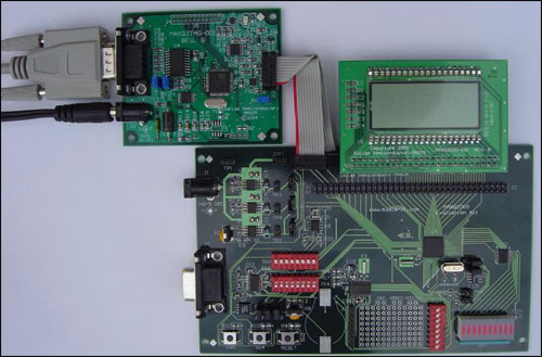
Figure 3. Correct connection of serial cable and JTAG board
Now you can start using the CrossWorks tool. Create MAXQ2000 project in CrossWorks Rowley Associates provides full-featured CrossWorks for MAXQ (30-day evaluation license), which can be downloaded from. Follow the prompts to install, select the default value for the installation location and other options. Note that Rowley Associates ’MAXQ CrossWorks is currently only available on the Windows platform. You need to send an email to Rowley Associates to request a 30-day product activation key before you can continue the installation. Follow the instructions in the "Support" section of the Rowley Associates website: Evaluate CrossWorks (EvaluaTIng CrossWorks).
After the installation is complete, run MAXQ CrossWorks as follows, from the start menu, select Rowley Associates Limited, then CrossWorks MAXQ 1.0, and finally CrossStudio. After the main window opens, a summary of the functions of CrossWorks will be displayed.
When creating a project, first select File, then New, and then New Project. In the dialog box that appears, select C Executable from the template, enter the name and location of the new project, and click OK (see Figure 4). 
Figure 4. New project options dialog window
In the next project settings dialog (see Figure 5), confirm that the Target Processor option is MAXQ2000. Other settings can keep the default values. Click Finish to generate a new MAXQ2000 project. 
Figure 5. New project settings dialog window
Then, you need to enter enough code to let the MAXQ2000 evaluation board do something interesting. If the Project Manager window is not open, select View, and then select Project Explorer to open it. You can now double-click the main.c file in the Project Manager window. Enter the following code (first delete the original code of main.c). #include
Once the serial-JTAG board is ready to connect, select Build, then select Build and Run from the menu to create and execute the project code. A series of messages ending with Verify Completed should appear in the output window; the LCD segment display on the MAXQ2000 evaluation board should display the conversion information as the code runs.
The above code demonstrates various functions of MAXQ CrossWorks. First, all registers of MAXQ2000 are predefined in the include file MAXQ2000.h. CrossWorks includes this file in the directory% Program Files% \ Rowley Associates Limited \ CrossWorks MAXQ 1.0 \ include when shipped from the factory. This directory is automatically searched when the project is compiled, so it is not necessary to copy MAXQ2000.h to the directory containing the project.
After the MAXQ2000.h file is included in the project, the code can directly access all MAXQ2000 internal registers through C language. As mentioned above, these registers are LCRA, LCFG, LCD0, LCD1, LCD2, and LCD3. For the list of all system and peripheral registers supported by MAXQ2000, see the MAXQ2000 User Guide Supplement (English only).
Note: Registers with built-in brackets in the name, such as A [0] and DP [0], must be referenced with underlined names in CrossWorks, such as A_0 and DP_0. In addition, it may not be possible to directly set independent register bits with C code, for example, IMR.0 = 0 is not allowed. Functions of the MAXQ2000 Evaluation Board Before we further understand the CrossWorks debugger, we will create a more complex application to demonstrate some of the functions of the MAXQ2000 evaluation board. The sample code can be downloaded.
This application displays the running counter value on the LCD and continuously counts up or down like a stopwatch. The counter value reverses when it reaches 19999 (the maximum value that can be displayed on the LCD). The two buttons on the MAXQ2000 evaluation board are programmed as control switches for this application: Press SW5 to reset the counter value to 0000. Press SW4 to reverse the counter. If the original count up, it will become a count down, and vice versa. If the count value is below 0, it reverses to 19999. To change the application code, right-click main.c in the Project Manager window and select Remove in the pop-up menu. Next, right-click on Source Files and select Add ExisTIng File. Select the demo2000.c file downloaded from the above link. After the file is added to the project, select Build, and then select Build and Run in the menu. The new application will be compiled, downloaded and run on the MAXQ2000 evaluation board. After the application starts to run, check and confirm that all the DIP switches on the board should be turned off except SW6.2 and SW6.5.
You can now demonstrate a more useful feature of the MAXQ2000 evaluation board, which is the RESET button. There is a switch labeled SW2 and RESET on the lower left side of the MAXQ2000 evaluation board. Press this button to observe the LCD screen. The reading should restart from 0 immediately. The RESET button is connected to the reset pin of MAXQ2000. If you need to restart the application, press this button. Initialize the LCD controller of MAXQ2000 MAXQ2000 provides a liquid crystal display (LCD) hardware control module, which can run in full bias, 1/2 bias and 1/3 bias modes to achieve static, x2, x3 or x4 multiplex the way. In other words, on the x4 multiplexed display, the MAXQ2000-RAX (COM0 to COM3, SEG0 to SEG32) can be dedicated to the LCD drive function of 37 lines can drive up to 132 LCD segments (33 segments X 4 common signals) .
Each opened LCD segment requires a continuous voltage waveform to drive, the voltage waveform is provided by the segment line connecting the segment and the common signal line. The driving voltage waveform enables each segment to be turned on or off as required without generating a DC bias voltage that may damage the LCD. The MAXQ2000 LCD controller automatically generates these voltage waveforms in the background. In other words, when the display segment of the LCD changes, only the register contents of the LCD controller need to be modified.
As in the example above, the first step is to initialize the LCD controller registers used to control the display. void initLCD (void) {LCRA = 0x03E0; // Set LCD configuration LCFG = 0xF3; // Set up all segments as outputs, normal operation // mode, and enable display.} LCRA register controls 3 important functions: display form, In this case, it is static; the adjustable resistance between VADJ and ground is used to modify the display contrast; and the frequency of the LCD segment drive waveform. The LCFG register controls the on / off of the LCD controller and controls which dual-purpose pins are used as port pins and which are used as LCD segments. Write the value to the display. Each LCD segment is controlled by one bit of an LCD control display register, regardless of the type of LCD and the multiplexing method used. When this position is high, the segment is opened (black); clear this bit to close (transparent) the segment. The relationship between the LCD segment and the memory mapping used by our MAXQ2000 evaluation board is shown in Figure 6. 
Figure 6. Mapping relationship between LCD segment and LCD display storage register bit
Each bit of the LCD occupies an LCD display storage register, and the distribution of each bit is the same. Therefore, we can use the lookup table to find the segment register value of each bit from 0 to 9, and write this value to the LCD display register. #define LCD_PATTERN_0 0x03F #define LCD_PATTERN_1 0x006 #define LCD_PATTERN_2 0x05B #define LCD_PATTERN_3 0x04F #define LCD_PATTERN_4 0x066 #define LCD_PATTERN_5 0x06D #define LCD_PATTERN_6 0x07D #define LCD_PATTERN_7 0x007 #define LCD_PATTERN_8 0x07F #define LCD_PATTERN_9 0x067 int PATTERNS [] = {LCD_PATTERN_0, LCD_PATTERN_1, LCD_PATTERN_2, LCD_PATTERN_3, LCD_PATTERN_4, LCD_PATTERN_5, LCD_PATTERN_6, LCD_PATTERN_7, LCD_PATTERN_8, LCD_PATTERN_9}; / ******************************** ********************************************** * Returns the value that will need to be placed in one of LCD0-LCD3 to display * a digit 0-9. No bounds checking is done here. If you ask for a digit other * than 0-9, you will get a bogus display. * / int getLCDDigit (int digit) {return PATTERNS [digit];} After these programs are ready, we can use the following method to write the counter value to the display (4 digits, in special cases "1" corresponds to the 5th digit): int show (int value) {if (value> = 10000) LCD4 = 0x40; else LCD4 = 0; LCD3 = getLCDDigit ((value / 1000)% 10); LCD2 = getLCDDigit ((value / 100)% 10); LCD1 = getLCDDigit ((value / 10)% 10); LCD0 = getLCDDigit ((value)% 10); return 0;} Debounce button input buttons SW4 and SW5 are the other two human-computer interaction components of this application, which are connected to port pins P5.2 and P7.1 through DIP switch part SW6, respectively. (The RESET switch does not require programming support, it is directly connected to the MAXQ2000 active low reset pin).
The power-up default mode of all MAXQ2000 port pins (except P4.0 to P4.3 corresponding to the JTAG interface) is input mode, and there is an internal weak pull-up between the port pin and VDDIO. The connection method of SW4 and SW5 switches is to pull the port pin to ground when pressed, so the port pin is already the configuration method we need. The port pin status can be easily obtained by checking the port pin input bit (PI5.2 for SW4 and PI7.1 for SW5); when the bit value is 0, the button is pressed, and when it is 1, the button is released.
However, because these switches are mechanically structured, a single press operation may cause multiple 0 to 1 transitions. To avoid this situation, you can use the existing main loop and delay as function modules to implement some simple debounce operations. while (1) {for (i = 0; i <32000; i ++) {// just a delay loop} show (counter); if (((PI5 & 0x04) == 0) && (debounce1 == 0)) {inc * = -1; debounce1 = 20;} if (((PI7 & 0x02) == 0) && (debounce2 == 0)) {counter = 0; debounce2 = 20;} counter + = inc; if (counter > 19999) {counter = 0;} if (counter <0) {counter = 19999;} if ((debounce1> 0) && ((PI5 & 0x04) == 0x04)) {debounce1--;} if ((debounce2 > 0) && ((PI7 & 0x02) == 0x02)) {debounce2--;}} When the switch changes from high to low, set a debounce counter. The high state of the switch must be maintained for 20 main counter count cycles before accepting the next high-to-low transition. In addition to the debounce function of the switch, the debounce counter also ensures that the function operation will not be repeated when the button is kept pressed; the switch must be released to be pressed again. Using the CrossWorks debugger Because the program is already running on the MAXQ2000, we can check the function of the CrossWorks debugging system. The JTAG interface that loads code into MAXQ2000 also supports many hardware debugging functions. Some examples include the following: Instruction single-step execution Execution address breakpoints (you can have 4 valid breakpoints at the same time) Direct reading and writing of register code and stack memory browsing Data memory browsing and direct editing These debugging capabilities can be debugged in the system with little impact on the processor resources provided to the application. A dedicated JTAG interface is used to complete this function, and there is no need to use other interfaces (such as the UART port on the MAXQ2000) to communicate with the host system. In addition, the breakpoint mechanism runs completely in the background, as long as the debugger does not stop the MAXQ2000, it will always run at full speed. When MAXQ2000 is running, you can even add, delete, or modify breakpoints, completely in the background.
CrossWorks uses these hardware debugging functions to provide C and assembly-level source code debugging, with complete debugging functions, such as setting breakpoints, observing variables and registers, and memory browsing and editing modes. To debug the program, first select Build, then select Build and Debug in the menu. Compile and download the application program to the MAXQ2000 evaluation board, and finally stop running in the main () function (see Figure 7). 
Figure 7. CrossWorks debug mode
In Figure 7 you can see the multiple functions of the CrossWorks debugger. A yellow arrow on the left side of the page indicates the current execution position. All executable positions (not including comments, blank space and some brackets) are shown by the blue triangle on the left. Local variables and their values ​​are also shown on the right side of the application code. These values ​​can be edited by clicking on the value and entering a new value. The red light to the right of the MAXQ Serial To JTAG tag at the bottom of the screen indicates that the application is stopped. At this point, there are multiple options to continue execution. Step Into (F11) executes a line and can step through the code. If the line contains a function call, step into the function and go to the beginning of the function. Step Over (F10) also executes a line if the line does not include a function call. If there is a function call, execute the function continuously (execute the function instead of skipping it) and stop at the next line of the function call. Step Out (Shift + F11) can only be used within a certain function (not the topmost function main ()). The function will continue to execute the rest of the function and stop at the line below the line that called the function. Run to Cursor (Control + F10) to the cursor position. The cursor must be on the executable code line to use this function. You can also select Go (F5) to run the program at a normal rate. At this time, it can run normally without debugging control. When the program is running, the indicator next to the MAXQ Serial To JTAG logo at the bottom is green, indicating that the application is running freely, but the debugger can interrupt and stop the program if necessary. There are two main methods to suspend application operation and re-debug control. The Break command (Control + ".") Will stop the application immediately, no matter where it is at the time. Left-click on the blue triangle mark of any executable code line to set a breakpoint in the corresponding position of the application. This will turn the blue triangle into a red circle. After the application runs to the breakpoint, it will stop running and enter debug mode again. Up to 4 breakpoints can be set or cleared when the program is stopped or running. (Note that because different step debugging functions occupy a breakpoint, if single-step debugging mode is used, only 3 breakpoints can be set). Finally, select Stop (Shift + F5) to terminate the debugging process and return the application to free running.
In the debug mode, there are 3 different ways to view the application: li> Source code mode (Control + T, S) displays the program in C code only. Assembly mode (Control + T, A) is displayed in assembly language. Stepping and breakpoint functions can be used for a single assembly line. Interleaved mode (Control + T, I) (see Figure 8) displays both C and assembly code in the same window. 
Figure 8. Debugging in interactive mode When the register window application is stopped in debug mode, you can view and edit the MAXQ2000 registers directly (see Figure 9). To open the display window, select Debug, and then select Debug Windows and Registers (1,2,3,4) in the menu. You can quickly browse through four different register windows; by clicking the Groups icon in the upper left, you can configure the window to display registers of different groups. 
Figure 9. Register window Using the Call Stack window Another debug window shows the current stack usage of the application (see Figure 10). This window lists all the calling functions that reach the current execution point of the code. The currently executing function is displayed at the end of the list, and the previous function that called the current function is displayed on the previous line. By analogy, it has been displayed in this display mode, and finally main () is displayed on the first line. To open this window, select Debug, then Debug Windows, and finally Call Stack, or press Control + Alt + S. 
Figure 10. Call Stack window Using variables and watch windows Debug and Debug Windows menus also provide other debug windows. The Locals and Globals windows display the local variable (current function or display range) value and global variable value, respectively. See Figure 7 above for the local variable display window. There is also a Watch window, which can be used not only to display variable values, but also to display the value of any C expression (see Figure 11). However, there can be no MAXQ2000 register in these expressions. Four Watch windows can be defined, each with its own list of variables and expressions. 
Figure 11. Watch window to view code and data memory memory window (select Debug, then Debug Windows, and finally Memory (1,2,3,4)) can be configured to display any code segment and data memory The current value. These values ​​will be updated after each step or when stopped at the breakpoint (see Figure 12). In addition, you can directly click on the data memory value and enter a new value for editing. 
Figure 12. Data storage window Support options The MAXQ platform provides multiple support options. Dallas Semiconductor developers manage an online discussion forum (English only) to answer questions from users. The forum is also a news release window for developers, it contains the latest available tool information and other questions of interest.
Dallas Semiconductor engineers provide two email addresses for issues that are not suitable for public discussion. var name = "micro.software @"; var domain = "dalsemi.com"; document.write ("" + name + domain + ""); micro. (English only) is managed by software engineers who can help solve MAXQ Microcontroller programming issues can help with the use of software tools such as Rowley Associates' CrossWorks. var name = "micro.support @"; var domain = "dalsemi.com"; document.write ("" + name + domain + ""); micro. (English only) is managed by application engineers who can assist with circuit resolution The hardware and design problems encountered in using the MAXQ microcontroller. For general news and information, as well as basic information about the MAXQ2000, MAXQ platform, and future MAXQ devices, please refer to the MAXQ homepage. Troubleshooting When using any new device, you will encounter some common problems. By checking the operating instructions in the first half of this document, many problems can be solved (such as circuit board connection and engineering configuration). Here are some other common problems and solutions.
Conclusion MAXQ2000 is a powerful, low-cost, low-power microcontroller with rich peripherals that supports multiple application systems. With the support of CrossWorks, the MAXQ development environment provided by Rowley Associates, complex applications can be written in C and debugged with the help of this powerful tool. In this way, high-quality products can be quickly introduced to the market. Problem Possible Solution When I compile my application, I get an "undeclared identifier" error each place I use a MAXQ2000 register. Make sure you have the line
#include
at the start of your application. When I select Connect MAXQ Serial to JTAG, I get a "Device is not responding" error. Make sure: that both boards are connected and powered up; that the JTAG cable connects with the red wire going to pin 1 on both sides; and that jumpers P2 (on the Serial-to-JTAG board) and JU11 (on the MAXQ2000 board ) are both closed. When I select Connect MAXQ Serial to JTAG, I get a "Cannot open serial link" error. Make sure no other software is using the COM port you have selected. Often, PDA software will own the serial port from the time you boot your computer. You can either choose a different COM port, or turn off your PDA software. The LCD segments are scrambled when I run the demo application. Make sure that the LCD daughterboard is hanging off the top side of the MAXQ2000 Evaluation kit, not in the position where it hangs downward over the center of the board.
Abstract: MAXQ2000 is a powerful, low-cost, low-power microcontroller with rich peripherals that supports multiple application systems. Rowley Associates provides a powerful MAXQ development environment CrossWorks. With the support of this tool, complex applications can be written and debugged in C language. This application note explains how to set up the MAXQ2000 evaluation board and get started with CrossWorks tools. As an application example, a simple counter is displayed on the LCD to demonstrate the functions of the MAXQ2000 evaluation board and CrossWorks. void main (void) {int i = 0; int j = 0; int k = 1; LCRA = 0x03E0; // Set LCD configuraTIon LCFG = 0xF3; // Set up all segments as outputs, normal operaTIon // mode, and enable display. while (1) {for (i = 0; i <500; i ++) {for (j = 0; j <500; j ++) {// delay loop}} k = (k << 1); if (k == 64) {k = 1;} LCD0 = k; LCD1 = k; LCD2 = k; LCD3 = k;}} After entering the above code, confirm that the MAXQ2000 evaluation board and serial port-JTAG board are connected according to the above instructions and Power-on. The status bar at the bottom of the CrossWorks window should indicate MAXQ Serial to JTAG, with a yellow light next to it. However, if Disconnected is indicated with a gray light next to it, you must connect to the serial-JTAG board by selecting Target and then selecting Connect MAXQ Serial to JTAG in the menu.