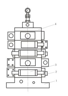
The InstallaTIon and ConnecTIon of Hydraulic Valve (1) Threaded ConnecTIon The valve with thread on the body port is called Tubular Valve. Connect the oil port of the pipe valve to the pipe with a threaded pipe joint and thus fix it on the pipe. This connection method is suitable for simple hydraulic systems with small flow. The advantages are: simple connection mode, convenient layout, and clear oil circuit between valves in the system. The disadvantages are: the components are dispersedly arranged, occupying a large space, the pipelines are interlaced, the connectors are numerous, and it is not convenient for loading, unloading and maintenance. (2) Flange ConnecTIon It is connected to the flange of the end of the pipe through the screw holes (more than 4 screw holes per oil port) on the valve body, and is connected together with screws. This valve is called a flanged valve. It is suitable for large flow hydraulic systems with a diameter of more than 32mm. Its advantages and disadvantages are the same as the thread connection. (3) Subplate Mounting The oil ports of the valve are arranged on the same installation plane, and there are holes for connecting screws. This kind of valve is called a plate valve. For example, the electromagnetic directional valve is mostly a plate valve (Subplate Mounting). Fix the plate valve with a screw on the plate or valve block type connector with the corresponding oil port. The advantage of this connection method is that it is convenient to replace components, does not affect the pipeline, and it is possible to centrally arrange the valves. The connecting body connected with the plate valve has two forms: connecting plate and integrated block. â‘ Connect the board. Fix the plate valve on the connection plate, and the oil passage between the valves is connected to the pipe with a pipe joint behind the plate. This kind of connecting plate is simple, and it is more convenient to check the oil circuit, but there are many oil pipes on the plate, which is extremely troublesome to assemble and takes up a lot of space. Figure 5.28 Integrated block hydraulic device 1- bottom plate; 2- integrated block; 3- valve; 4- cover plate Figure 5.29 Superimposed valve hydraulic device 1- Base plate; 2- Pressure gauge switch (Piezometer Switch); 3- Directional valve â‘¡ Manifold block. The integrated block is a positive six-sided connector. The plate valve is fixed on the three sides of the integrated block with screws. Usually, a valve is installed on each of the three sides. Sometimes a simple valve can be installed between the valve and the integrated block, such as a check valve and a throttle valve. Wait. The remaining side is equipped with oil pipes to connect the actuators. The upper and lower sides of the integrated block are the joint surfaces of the block and the block. Common oil holes are drilled in the vertical direction of the same coordinate position on the joint surface of each integrated block: pressure oil hole P, oil return hole T, leakage oil hole L and Holes for mounting bolts, and sometimes pressure measuring oil holes. Each oil port on the joint surface between the block and the block and the valve is sealed with an O-ring. Drill holes in the integrated block to communicate with each valve to form a loop. Each integrated block and the valve components installed around it form an integrated block group. Each integrated block group is a typical circuit. According to the different requirements of various hydraulic systems, select a number of different integrated block groups and stack them together (see Figure 5.28) to form the entire integrated block type hydraulic device. The advantages of this integration method are: compact structure, small footprint, easy loading and unloading and maintenance, the design of the hydraulic system can be simplified to the selection of integrated block groups, so it is widely used. However, it also has the disadvantages of large design workload, complicated processing, and inability to modify the system at will. (4) Superimposed connection Sandwich Plate Design The upper and lower surfaces of various hydraulic valves are used as the connecting surface like the bottom surface of the plate valve. The connecting surface of various hydraulic valves of the same specification has the same position of the oil port, screw hole, and connection size (reversing according to the same specification) The connection size of the valve is determined), this valve is called a superposition valve (Superposition Valve). According to the requirements of the system, the stacking valves of various functions with the same specifications are stacked in a certain order to form a stacking valve hydraulic device, as shown in Figure 5.29. The bottom of the superimposed valve type hydraulic device is generally a bottom block. The bottom block is provided with an oil inlet P, a oil return port T, and oil ports A, B and a pressure gauge oil port leading to the actuator. A stacking valve group generally controls an actuator. If there are several actuators in the system that require centralized control, several vertically stacked valve groups can be arranged side by side on the multi-connected bottom plate. In the hydraulic system composed of superimposed valves, the connection between the components does not use pipes or other forms of connecting bodies, so the structure is compact, the volume is small, the leakage loss and pressure loss of the system are small, especially the hydraulic system is more convenient to change, flexible. The superposition valve is a standardized component. In the design, only the schematic diagram of the superposition valve hydraulic system needs to be drawn to assemble, so the design workload is small and the application is wide. (5) Cartridge Fitting The valve is made into a cylindrical special element (with the valve body removed)-Cartridge Valve. The plug-in valve is directly inserted into the socket hole of the valve block (integrated block, block) with a channel, to form a hydraulic system. Its structure is very compact. Various pressure valves (Pressure Control Valve), flow valves (Flow Control Valve), directional valves (Directional Control Valve), proportional valves (Proportional Valve), etc. can be made into cartridge valves.
Portable power supply humanized output port design: AC dual output port 220V output, to solve multi-channel power demand; DC 24V, 12V cigarette lighter, dual 5V USB output, more widely used. Can meet the needs of most electrical appliances, such as energy storage system for LED Light,energy storage system for outdoor, energy storage system for medical equipment,mobile phones, telephones, digital cameras, mobile hard drives, digital cameras, tablets, laptops, car starters, pumps, postal and telecommunications, environmental instruments Etc; can also be used in the following areas such as: finance, first aid, excavation, exploration, military, science, media, tourism, disaster relief, medical assistance, environmental protection and areas with widespread power shortages.
Portable Energy Storage System Portable Storage,Ac Rechargeable Battery,Portable Energy Storage System,Outdoor Portable Energy Storage System,Portable Battery With AC/DC Output,High Capacity Portable Battery Shenzhen Enershare Technology Co.,Ltd , https://www.enersharepower.com
There are five ways to connect hydraulic valves.