LCD TV LCD TV backlight design analysis Abstract: LCD (liquid crystal display) is an electronically controlled luminous tube. LCD TV (liquid crystal display TV) uses white light as a "backlight", usually using cold cathode fluorescent lamps (CCFL) to illuminate color fluorescent screens. Other technologies, such as light-emitting diodes (LEDs), are also considered as a solution, but their high price limits their use.
Automotive Toggle Switches
Automotive Toggle Switches , namely Electrical Toggle Switches. Our Automotive Switches could divided into Push Button Switches, Automotive Toggle Switches, Automotive Rocker Switches, Automotive Rotary Switches and Automotive Battery Switches .
Yeswitch has been designing and manufacturing Momentary Toggle Switches for nearly 30 years and has accumulated rich experience in this field. Yueswitch people continue to innovate and constantly overcome technical problems, providing professional automotive control panel toggle switches for global automakers and enthusiasts in the global automotive modification industry. The types of our toggle switch products are complete and diversified to meet the needs of customers.
Yeswitch Waterproof Toggle Switches is widely used in the automotive field, ship, medical, communication, and has IP6 standard. Our company's full range of toggle switches not only have reliable quality assurance, but also can be diversified in appearance. Different types of crank handles can be selected with LED Light design, which is convenient for setting and preventing desperation.
Automotive Toggle Switches Automotive Toggle Switches,Automotive Toggle Switch,Electrical Toggle Switches,Toggle Switch Function YESWITCH ELECTRONICS CO., LTD. , https://www.yeswitches.com
This article focuses on the design challenges of driving and controlling multiple CCFLs to provide backlighting for large LCD panels (such as LCD TVs).
Table 1. Comparison of CCFL drive architecture Drive Architecture Advantages Disadvantages Royer Least expensive Cannot TIghtly control the lamp current or frequency Requires TIght DC-supply regulaTIon Requires a special transformer winding Requires a ballst capacitor Low efficiency Full Bridge Does not require a center-tapped transformer Works over a wide DC-supply range (greater than 3: 1) Requires four MOSFETs May require p-channel MOSFETs, which are higher cost and less efficient Half Bridge Requires only two MOSFETs May require p-channel MOSFETs, which are higher cost and less efficient Requires a higher turns raTIo transformer, which increases cost Push-Pull Requires only two n-channel MOSFETs, which are lower in cost and more highly efficient than p-channel MOSFETs Easily scales to higher DC supply voltages (up to 120V) Low transformer turns ratio Lower efficiency when the DC supply goes beyond a 2: 1 range
Royer architecture The best application of the Royer architecture (Figure 1) is in designs that do not require strict control of lamp frequency and brightness. Because the Royer architecture is a self-excited design, it is difficult to strictly control the lamp frequency and lamp current due to the deviation of component parameters, and both of them will directly affect the brightness of the lamp. Because of this, the Royer architecture is rarely used in LCD TVs, although it is the cheapest of the four architectures described in this article. 
Figure 1. The Royer driver is simple, but not very accurate.
Full-bridge architecture The full-bridge architecture is best suited for applications with very wide DC supply voltages (Figure 2). This is why almost all notebook PCs use the full-bridge approach. In notebooks, the DC power supply of the inverter comes directly from the main DC power supply of the system, which usually ranges from 7V (low battery) to 21V (AC adapter). Some full-bridge solutions require the use of p-channel MOSFETs, which are more expensive than n-channel MOSFETs. In addition, due to the inherent high on-resistance, the efficiency of p-channel MOSFETs is lower. 
Figure 2. The full-bridge driver is well suited for a wide range of DC power supplies.
Compared with the full-bridge half-bridge architecture, the biggest advantage of the half-bridge architecture is that two MOSFETs are used per channel (Figure 3). However, it requires a transformer with a higher turn ratio, which increases the cost of the transformer. Also, like the full-bridge architecture, the p-channel MOSFET may also be used in the half-bridge architecture. 
Figure 3. Half-bridge drivers use two MOSFETs less than full-bridge drivers.
Push-pull architecture Finally, let's consider the push-pull driver, which has many benefits. This architecture uses only n-channel MOSFETs (Figure 4), which helps reduce costs and increase inverter efficiency. It is easy to adapt to higher inverter DC power supply voltage. When a higher inverter DC power supply voltage is used, it is only necessary to select a MOSFET with an appropriate drain-source breakdown voltage. Regardless of the DC power supply voltage of the inverter, the same CCFL controller can be used. However, the full-bridge and half-bridge architectures using n-channel MOSFETs cannot do this.
The biggest disadvantage of the push-pull architecture is that the range of the DC power supply voltage of the inverter is required to be less than 2: 1. Otherwise, when the DC power supply voltage is at the high end, the efficiency of the system will decrease due to the high amplitude factor of the AC waveform. This makes the push-pull architecture unsuitable for notebook PCs, but it is ideal for LCD TVs because the DC power supply voltage of the inverter is usually stabilized at ± 20%. 
Figure 4. The push-pull driver is very simple and can be precisely controlled.
The multi-lamp driver CCFL has been used in notebook PCs, digital cameras, navigation systems, and other devices with smaller LCD screens for many years. These types of devices usually use only one CCFL, so traditional designs use only one CCFL controller. With the emergence of large-size LCD panels, there is a demand for multiple CCFLs, and it is necessary to adopt new ways to respond to this new demand. One of the possible ways is to use a single channel CCFL controller to drive multiple lamps (Figure 5). In this way, the CCFL controller monitors the lamp current through only one of the lamps, and drives all lamps in parallel with almost the same AC waveform. However, this approach has several drawbacks. 
Figure 5. Due to uneven brightness and other considerations, it is not ideal to control multiple lamps with a single channel CCFL controller.
The first problem is how to keep the brightness of all the lights uniform, so that the display does not show obvious bright and dark areas. Driving all lamps with the same waveform will cause the current of each lamp to be different, thus causing a difference in brightness. Due to the difference in lamp impedance, using the same waveform will cause uneven brightness. Moreover, the brightness of the CCFL varies with temperature (Figure 6). As the heat rises, the lamp at the top of the panel (see Supplementary Materials, Figure 12) will be hotter than the lamp at the bottom of the panel, which will also cause uneven brightness. 
Figure 6. The brightness of the CCFL varies with ambient temperature.
The second disadvantage of using a single channel CCFL controller to drive multiple lamps is that the failure (eg damage) of a single lamp will cause all lamps to turn off. The third disadvantage is that all lamps are driven in parallel and turned on and off at the same time, which requires that the inverter DC power supply must be decoupled more heavily and use a larger smoothing capacitor. This will increase the cost and size of the inverter.
One way to solve the above problems is to use a separate CCFL controller for each lamp (Figure 7). However, the main disadvantage of this approach is that the additional CCFL controller brings additional costs. The ideal solution for providing illumination to an LCD panel is a multi-channel CCFL controller, which drives and monitors each lamp independently for each channel (Figure 8). This multi-channel CCFL controller not only solves the problem of uneven brightness and single lamp failure, reduces the decoupling requirements, but also has high cost efficiency. 
Figure 7. Using a single-channel controller to drive each CCFL is not cost-effective. 
Figure 8. A multi-channel controller is ideal for controlling multiple lights.
Precision control of lamp frequency and dimming frequency Since LCD TVs need to display dynamic and continuously moving pictures, it has some special requirements that are not found in static display applications (such as computer monitors and notebook PCs). The driving frequency of CCFL may interfere with the picture displayed on the LCD screen. If the light frequency is close to a certain multiple of the video refresh rate, a slowly moving line or band will appear on the screen. By precisely controlling the lamp frequency to within ± 5%, this defect can be eliminated.
The sudden dimming frequency used to adjust the brightness of the lamp also requires the same precision control. This dimming method usually uses a pulse width modulation (PWM) signal in the frequency range of 30Hz to 200Hz to turn off the lamp in a short time to achieve the purpose of dimming. Because the turn-off time is very short, it is not enough to make the ionization state disappear. If the burst dimming frequency is close to the multiple of the vertical synchronization frequency, rolling lines will also be generated. Similarly, strictly controlling the burst dimming frequency within ± 5% can eliminate this problem. In addition, in some LCD TVs, in order to improve the image response of the LCD screen, the slow CCFL burst dimming frequency is also required to be synchronized with the video vertical synchronization frequency.
Solutions to the LCD TV backlight challenges (DS3984 / DS3988) The DS3984 (four-channel) and DS3988 (eight-channel) CCFL controllers solve all these design challenges mentioned in this article. These devices can be configured to drive one lamp per channel (Figure 9), or multiple lamps per channel (Figure 10), users can flexibly reduce the design to meet their own cost performance goals. Multiple DS3984 / DS3988 can be easily cascaded to support any number of lamps to provide backlighting for LCD TV screens.
DS3984 / DS3988 adopts push-pull drive architecture, which can use lower cost, higher efficiency n-channel MOSFET. Inverter DC power supply can also use higher voltage. Individual lamp control and monitoring provide uniform brightness and reduce the total number of inverter components. When using a separate lamp control, if a certain lamp fails, it will only stop the failed lamp, and the other lamps will continue to operate without being affected. The lamp frequency and burst dimming frequency generated by the on-chip oscillator are strictly regulated to a precision level of ± 5%, eliminating the effect on the displayed image, and can also be synchronized to an external clock source. 
Click to enlarge Figure 9. The DS3984 / DS3988 individually drive and monitor each lamp to provide uniform brightness for LCD TVs and PC monitors. 
Click for larger image Figure 10. Each channel of the DS3984 / DS3988 can also drive multiple lamps.
CCFL cold cathode fluorescent lamp (CCFL) is a long and thin sealed glass tube filled with inert gas (Figure 11). When a high voltage is applied to the lamp tube, the gas is ionized, generating ultraviolet (UV) light. Ultraviolet rays hit the fluorescent material coated on the inner wall to excite it and emit visible light. CCFL has many advantages, including:
Excellent white light source, low cost and high efficiency (ratio of light output to input electric power), long life (> 25 thousand hours), stable, determined working state, easy to adjust brightness, light weight 
Figure 11. CCFL is a glass tube filled with inert gas.
CCFL has some special properties that must be carefully considered to maximize its efficiency, life, and practicality. However, these characteristics bring some special design challenges. For example, in order to maximize the life of the lamp, an AC waveform needs to be used to drive the CCFL. Any DC component will cause a part of the gas to gather at one end of the tube, causing an irreversible light gradient, making one end of the tube brighter than the other. Also, in order to maximize its efficiency (ratio of light output to input electric power), it is necessary to drive the lamp tube with a nearly sinusoidal waveform. For this reason, CCFL usually needs a DC-AC inverter to change the DC power supply voltage into an AC waveform of 40kHz to 80kHz, and the operating voltage is usually 500VRMS to 1000VRMS.
A typical CCFL layout in an LCD TV. Figure 12 shows how CCFLs are usually arranged in an LCD TV. The 12 lamps in this TV are evenly spaced across the LCD backplane to provide the best light distribution. It is important that all lamps work at the same brightness. Although a diffuser is arranged between the CCFL tube and the LCD panel to help evenly distribute the backlight, uneven tube brightness is still easily noticeable and affects the image quality of the TV. Depending on the size of the LCD panel, the number of CCFL lamps used may be as much as 30 or even 40. 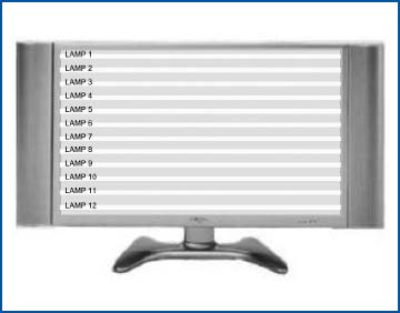
Figure 12. There are 4 to 40 CCFLs in an LCD TV.

