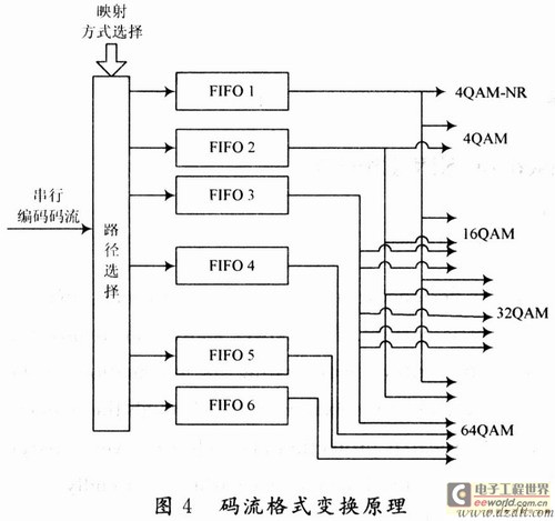
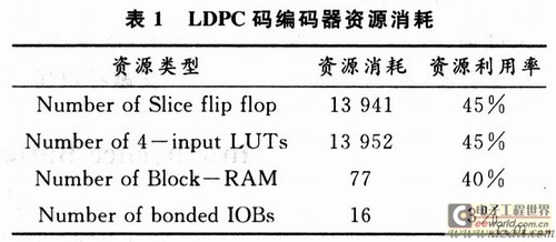
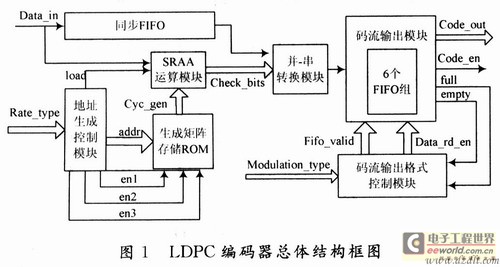
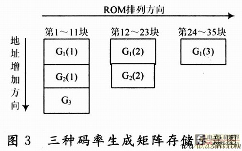
Realization of a multi-rate LDPC encoder with controllable output format 0 Preface At present, LDPC codes have been widely used in deep space communication, optical fiber communication, digital audio and video broadcasting and other fields. Because of its better performance than Turbo codes, LDPC codes have become a strong competitor of the fourth-generation mobile communication (4G) system channel coding scheme. In the digital TV terrestrial broadcasting system, in order to meet the user requirements of different channel conditions and different receiving devices, channel coding often needs to cooperate with multiple modulation methods. So that it can be applied flexibly in different occasions. This requires that the width of the output code stream of the channel coding module of the communication system has a certain flexibility, provides the best code stream format for the coded symbol mapping module, improves the versatility of the encoder, and reduces the complexity of the symbol mapping design. China's digital TV terrestrial broadcasting standard (DTMB standard) uses three LDPC codes and five different symbol mapping methods. For better versatility, LDPC encoders not only need to support three LDPC codes at the same time. And the output code stream format needs to be flexible and controllable, so as to meet the best code stream format of the five symbol mapping methods. Here mainly for this situation, the Verilog hardware description language is used to design and implement the LDPC encoder on the FPGA chip, and the correctness of the encoder is tested and verified. 1 LDPC coding and symbol mapping in the DTMB standard The LDPC code in the DTMB standard belongs to a quasi-cyclic LDPC code, and its generating matrix has the format shown in equation (1). In the formula: Gi, j is a b × b cyclic square matrix, 1 ≦ i ≦ kc, 1 ≦ j ≦ c; I is a unit matrix of b × b; o is a b × b zero square matrix. The DTMB standard supports LDPC codes with three code rates of 0.4, 0.6, and 0.8. The generator matrix Gqc of the LDPC (7493, 3048) code with a code rate of 0.4 has parameters k = 24, c = 35, and b = 127; the generator matrix Gqc of the LDPC (7493.4452) code with a code rate of 0.6 The generator matrix Gqc with parameters k = 36, c = 23 and b = 127; LDPC (7493,6096) code with a code rate of 0.8 has parameters k = 48, c = 11 and b = 127. Assuming that the information sequence is S and the codeword sequence is C, the LDPC encoding can use the equation C = S × Gqc. It can be seen from the characteristics of the system code that the information sequence is multiplied by the first half of Gqc to obtain the check digit, and then the information sequence is added after the check digit to be the code word sequence. The specific method for finding the check digit is that the information sequence S is multiplied by the first column of Gqc to get the first check digit, the information sequence S is multiplied by the second column of Gqc to get the second check digit, and so on until In column c-1, all c check digits can be obtained. After the code stream in the DTMB system is LDPC encoded, the first five check bits are deleted, and then mapped into a uniform symbol stream. The DTMB standard includes 64QAM, 32QAM, 16QAM, 4QAM, and 4QAM = NR five symbol mapping relationships. Various symbol mappings add corresponding power normalization factors to make the average power of various symbol mappings converge. For 64QAM, since every 6 b corresponds to 1 constellation symbol, the optimal input code stream width is 6. Similarly, for 32QAM, every 5 b corresponds to 1 constellation symbol, and the optimal input stream width is 5; for 16QAM, every 4 b corresponds to 1 constellation symbol, and the optimal code stream width is 4; for 4QAM, each 2 b corresponds to 1 constellation symbol, and the optimal input stream width is 2. The 4QAM-NR mapping method needs to add NR quasi-orthogonal coding mapping before the 4QAM symbol mapping. Since the encoded data is first subjected to bit-based convolutional interleaving, the best input stream format is serial data. 2 Design and implementation of encoder From the previous analysis, it can be seen that the LDPC encoder not only needs to support three bit rate encoding at the same time, but in order to achieve the best cooperation with the symbol mapping method, the encoded output stream must support 1, 2, 4, 5, 6 bits Controllable. Using the hardware implementation scheme of Figure 1, the entire encoder can be divided into 7 modules. (2) Generate matrix storage module. The generator matrix G1, G2, G3 of the three code rates in the DTMB standard, the total number of bits to be stored is fixed. If stored according to a general scheme, then 35 parallel SRAA circuits must correspond to a storage space with a width of 35 × 127 = 4 445 and a depth of 24 + 36 + 48 = 108. Aiming at the characteristics of the long and narrow structure of the BlockRAM in the FPGA with a large depth and a small width, if the stored data has a large width and a small depth, it will cause a lot of waste of storage resources in the FPGA. Therefore, the storage scheme shown in FIG. 3 is adopted here. The data used by each SRAA circuit is stored in a ROM, so that only 35 storage structures are needed, the width of the first to 11th is 127, the depth is 24 + 36 + 48 = 108; the width of the 2nd to 23rd is 127, the depth is 24 + 36 = 60; the width of the 24th to 35th is 127, and the depth is 48. (4) Parallel / serial conversion module. The output of the SRAA circuit is parallel data, and parallel-to-serial conversion is performed on the parallel data, so that the code stream control module controls the format of the output code stream. (5) Synchronous FIFO. The DTMB standard LDPC code is a system code. When outputting, the information bit is the last and the check bit is the first, so the information input sequence needs to be cached. After the parity bit is output, the dare information bit is read from the synchronous FIFO and appended to the parity bit to form a complete code word. (6) Code stream output module. In order to achieve the best match with the symbol mapping method, the encoder output stream format must support 1, 2, 4, 5, 6 and 64QAM four symbol mapping methods, the optimal width of the encoder output is 2, 4, 5, 6. Considering the full use of the advantages of a large number of BlockRAM resources in FPGA, the idea based on ping-pong operation is adopted here, and six FIFOs with a width of 1 are used to realize the conversion of a serial data stream to a specified width data stream. The structural principle is shown in FIG. 4 . Taking the 4QAM mapping method after encoding as an example, the serial data stream is controlled by the output signal fifo_vaIid of the control module, the first data is stored in No. 1 FIFO, the second data is stored in No. 2 FIFO, and then the third data Stored in 1FIFO again, the fourth data is stored in No. 2 FIFO, so cycle until the FIFO is full, when the control module receives the full signal returned from the FIFO, the output signal data_rd_en opens the No. 1 and No. 2 FIFO is 2 bits and The input is serial, and the output speed is faster than the input. When the FIFO data is read empty, an empty signal is generated to notify the control module to stop reading the FIFO. Thereafter, the encoder outputs a 0 sequence, and at the same time outputs the data valid signal code_out_en to 0. Similarly, corresponding to 16QAM, 32QAM, 4QAM, and 64QAM, output code streams with widths of 4, 5, and 6 can be obtained. If you are using 4QAM-NR symbol mapping. Because the interleaving is required after encoding, the serial output of the code stream is the best choice, so the serial data does not need to be buffered by the FIFO group. Just output directly. (7) Code stream output format control module. According to the symbol mapping mode selected by the input pin mod-ulaTIon_type, the ping-pong operation of the code stream output module is realized. Generate control signals fifo_valid, data_rd_en, and receive the full and empty signals returned by the code stream output module at the same time, to achieve the purpose of controlling the width of the encoder output code stream. 3 Design results and verification The LDPC encoder here is implemented under Xilinx's XC4VSX35 FPGA chip. Pipelining, ping-pong operation, and other techniques are used in the design to increase the frequency of the system. The integrated hardware resource consumption is shown in Table 1. In the layout and routing, the corresponding pins and cycles are appropriately constrained. By using different frequencies of excitation as input for testing, the maximum operating frequency of the core part of the hardware circuit can reach about 83 MHz, which fully complies with the highest clock in the DTMB standard The frequency requirement is 7.56 × 6 = 45.36MHz. During verification, the LDPC code with a code rate of 0.4 and the output code stream format are 6-bit parallel behavior examples. The timing simulation results are shown in Figure 5. Save the output code stream sequence of a time sequence simulation in Testbench and compare it with the result of encoding in Matlab. The output of LDPC encoder is completely consistent with the result calculated by Matlab. In the same way, it can be verified that the encoding results of the LDPC encoder are correct under the different output formats of the other two code rates. 4 Conclusion A multi-rate LDPC encoder with a controllable code stream output format is implemented here, and the correctness of the encoder is verified. The encoder not only supports the LDPC codes of the three code rates in the DTMB standard, but the output code stream format has 1, 2, 4, 5, 6 bit widths to choose from, so as to achieve the -The best match of NR five symbol mapping methods, with good versatility, can be applied to the transmitter of DTMB system. 100 Watt Led Flood Lights Outdoor are DLC 4.3 Qualified and ETL-Listed, making them eligible for many utility, local, state, and federal LED retrofit rebates! 100 Watt LED Flood Light saves money, saves energy, and is rewarded in your energy efficient choice.The Flood Lights have an IP66 Rating which means that there`s complete protection against dust and powerful water jets. 100 watt Led Flood Lights Outdoor 100 Watt Led Flood Lights Outdoor,100 Watt Led Flood Light,Flood Lights Shenzhen Bbier Lighting Co., Ltd , https://www.chinabbier.com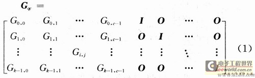
(1) Operation module. Responsible for the calculation of check digits. Each Gi, j matrix in equation (1) is a 127 × 127 square matrix, so the input information sequence can be divided into k segments of length 127, and the coding can be decomposed into k sub-processes. The core part of the coding adopts the serial input / parallel output SRAA circuit proposed in [7], as shown in Figure 2. Among them, B stores the generator polynomial of Gi and j (the first row of the matrix), and A is used to store the intermediate result of the operation. Since Gi and j in equation (1) are cyclic square matrices, each row of them is shifted to the right of the previous row, and the first row is shifted to the right by the last row; each column is shifted to the left Move down one bit, and the first column is the last column down one bit, so in every 126 clocks, the data in B performs a circular right shift every other clock. After 126 clocks, read in the next Gi, j Generator polynomial. Cyclic calculation in this way can get all check digits. Considering the encoding of the three code rates of 0.4, 0.6, and 0.8 in the DTMB standard separately, 35, 23, and 11 SRAA circuits are required in parallel to complete all check digit acquisition. Therefore, in order to realize the multiplexing of the three code rate encoder resources and comprehensively consider the operation speed, 35 parallel schemes of SRAA circuits are adopted here. 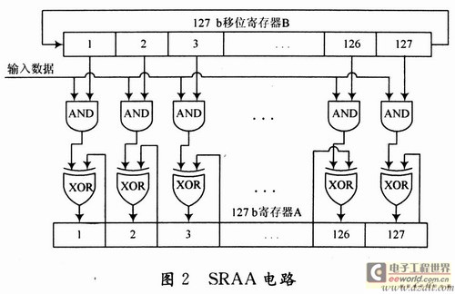
(3) Address generation control module. According to a certain timing, the output matrix stores the read address of the ROM, generates a load enable signal every 126 clocks, and reads out the generator polynomial required by the SRAA operation module from the ROM. At the same time, according to the different code rates, the ROM enable signal is generated, and the generator matrix storage blocks corresponding to the LDPC codes with different code rates are selected.