1 Introduction
RFID (Radio Frequency IdenTIficaTIon) is an automatic identification technology whose basic principle is to realize automatic recognition of recognized objects by using radio frequency signals and spatial coupling transmission characteristics. Compared with the existing bar code technology, the radio frequency identification technology has the advantages of high temperature resistance, waterproofness, repeated data writing, high security, and large data storage space. In recent years, with the rapid development of computer technology, chip technology and wireless communication technology, RFID technology has also been developed at a high speed, and its volume, cost and power consumption are getting lower and lower. The application system based on RFID technology is widely applied to various fields of life. Such as transportation, physical management, access control, positioning systems, second-generation ID cards and other fields. RFID systems generally consist of an antenna, a reader, and an electronic tag. The traditional RFID system uses a reader/writer and a PC host computer to communicate in a wired form (Ethernet, RS232), which has the disadvantages of poor flexibility, short data transmission distance, and high cost. Compared with the wired transmission system, ZigBee wireless transmission technology can realize wireless bidirectional transmission of data information, eliminating the trouble of wiring, and the ZigBee networking is efficient, fast and simple. In order to improve the transmission distance, flexibility and reduce system cost of RFID system, an electronic tag recognition system is designed based on ZigBee and RFID technology. The system test shows that the system has the advantages of low cost, high flexibility, long transmission distance and low power consumption, which expands the application of ZigBee technology in wireless RFID systems.
2 overall system design
The system hardware structure is mainly composed of five parts: active electronic tag, master-slave RF module with nRF24LE1 chip as microprocessor, ZigBee terminal node, ZigBee coordinator node and PC host computer. Figure 1 shows the overall structure of the system. Active electronic tag: records the ID number of the electronic tag and other item data information; the master-slave RF module: the RFID reader, is responsible for identifying the electronic tag data information within the range of the antenna radiation, and will receive the electronic tag information It can be transmitted to the ZigBee terminal node through the serial port, and can also receive the control commands transmitted from the ZigBee terminal node. The main RF module accepts the electronic tag ID information recognized by the RF module through the SPI to achieve dual channel transmission, which has better data accuracy and reliability. The ZigBee terminal node: the data information that the master and slave RF modules recognize to the electronic tag. The ZigBee coordinator node is wirelessly transmitted, and the ZigBee terminal node controls the master-slave radio frequency module according to the control command transmitted by the coordinator, thereby implementing corresponding processing on the electronic tag; the coordinator node: the electronic device that sends the ZigBee terminal node The tag data information is transmitted to the host computer through the serial port RS232, and the control command of the host computer is forwarded to the ZigBee terminal node; the PC host computer has corresponding application software, processes the tag information from the ZigBee coordinator node and sends the tag information to the ZigBee coordinator node. Control information.
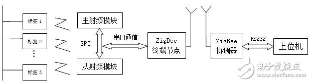
Figure 1 Overall structure of the system
3 system hardware design
3.1 System master-slave RF module circuit design
The system master-slave RF module is the core part of the RFID reader, and receives the control command issued by the ZigBee terminal node from the ZigBee coordinator node through the serial port, thereby controlling the data communication between the RF chip and the electronic tag, and completing the pair. Reading and writing of electronic tags. The radio frequency chip is responsible for the encoding and decoding, modulation and demodulation of the wireless signal; the electronic tag is the application terminal of the system, loading the data information of the object and the information of the tag itself, and receiving the wireless pulse from the reader antenna to receive the reader Control information, and then return the data information of the electronic tag to the reader through the antenna, and complete the reading and writing of the electronic tag data by the reader. The design of the master-slave RF module circuit ensures the accuracy and reliability of the electronic tag information recognized by the reader. The RF module circuit uses the nRF24LE1 chip, which is a wireless transceiver chip with enhanced 8051 core from Nordic. It can work in the 2.4-2.5GHz ISM band, without the communication cost of any channel, users do not need to apply for frequency. License for user application and development. The maximum air transmission rate is 2 Mbps, the sensitivity is -94 dBm, and the maximum signal transmission power is 0 dBm. In an ideal state, the indoor transmission distance can reach 30-40 m, and the outdoor transmission distance can reach 100-200 m. The operating voltage is 1.9 ~ 3.3V, which greatly reduces the power consumption of the system. The combination of processor power, memory, low-power crystal oscillators, real-time real-name, counters, AEC crypto accelerators, random number generators, and power-saving modes provides an ideal platform for implementing RF protocols. For the application layer, the nRF24LE1 provides a rich set of peripherals such as SPI, IIC, UART, 6 to 12-bit ADC, PWM, and an ultra-low-power analog comparator for voltage-level system wake-up. A master SPI, a slave SPI, implements dual channel data communication in an RFID system. The nRF24LE1 incorporates Enhanced ShockBurst technology, in which parameters such as communication channel, output power and number of automatic retransmissions can be programmed. The system master-slave RF module circuit is basically the same, and the software can be set as the main RF module. Figure 2 shows the RF circuit hardware structure diagram.
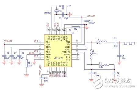
Figure 2 RF circuit hardware structure
3.2 ZigBee terminal node circuit design
The ZigBee terminal node is the hardware core of the contactless RFID reader and ZigBee wireless module in the system. It mainly controls the electronic tag to exchange data with the master-slave RF module and data communication with the ZigBee coordinator node. The terminal node circuit uses a 32MHz crystal oscillator as a clock signal, and communicates with the master-slave RF module through a serial port. ZigBee terminal node adopts CC2530 chip, which is a kind of RF transceiver which can be realized by TI company to realize 2.4GHz IEEE 802.15.4. It has the characteristics of high sensitivity and strong anti-interference ability, especially the ultra-low power consumption of CC2530 chip in passive mode. (RX), current consumption is 24mA, in active mode (TX), current loss is 29mA, with three modes, mode 1, mode 2 and mode 3 current losses are 0.2mA, 1uA and 0.4uA, respectively, especially suitable Those that require low power consumption. It also has a wide supply voltage range of 2V-3.6V. It includes an 8-bit MCU (8051), 8KB of RAM, a 12-bit analog-to-digital converter (ADC) with 8 inputs and configurable resolution, and a MAC timer that complies with the IEEE 802.5.4 specification. 1 regular 16-bit timer and 1 8-bit timer, AES-128 coprocessor, watchdog timer, 32kHz crystal sleep mode timer, power-on reset circuit, power-down detection circuit, and 21 Programmable I/O pin. Figure 3 shows the hardware circuit diagram of the ZigBee terminal node.
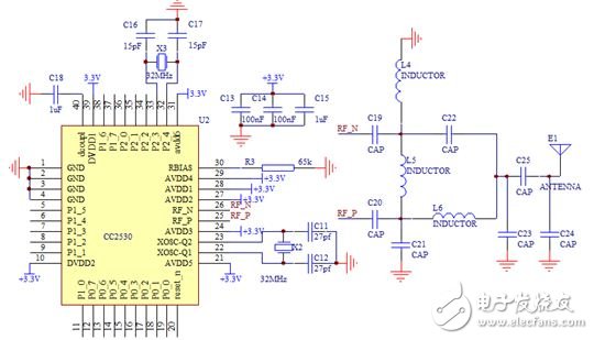
Figure 3 ZigBee terminal node hardware structure
3.3 ZigBee Coordinator Node Circuit Design
The ZigBee coordinator node is responsible for data communication between the ZigBee terminal node and the host computer through the RS232 serial line, and will receive the control command transmitted from the host computer and send it to the ZigBee terminal node. The ZigBee coordinator circuit diagram is identical to the ZigBee termination node circuit. As shown in Figure 3, it is only necessary to set it as a coordinator in the Z-stack protocol stack. Since the CC2530 uses TTL level and PC communication uses EIA level, the system uses MAX232 chip to achieve level conversion to ensure effective communication of the system, as shown in Figure 4.
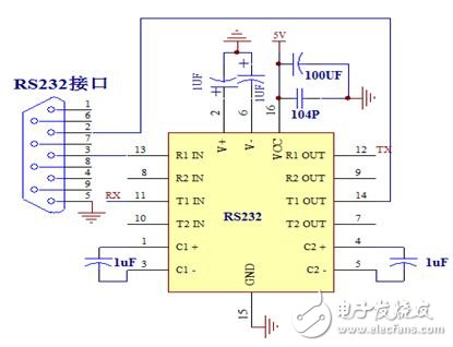
Figure 4 MAX232 level conversion circuit diagram
4 system software design
4.1 ZigBee terminal node software design
The main function of the terminal collection node is to receive the data collection instruction from the upper computer, collect the electronic tag data information, and send the collected data information to the coordinator node. First, the ZigBee terminal node is powered on and initialized to apply to join the established ZigBee network. If the network is successfully joined, the low-power mode is put into a sleep state to reduce the power consumption of the terminal node. Waiting for the timing interrupt to occur, the ZigBee terminal node microprocessor controls the master-slave radio module to read the electronic tag information, and transmits the identified tag data information to the ZigBee coordinator node through the ZigBee wireless module, and then transmits it to the host computer through the serial port RS232. Process it. The flow chart of the terminal collection node program is shown in Figure 5.
![Figure 5 ZigBee terminal acquisition node software flow chart]()
Figure 5 ZigBee terminal acquisition node software flow chart
4.2 ZigBee Coordinator Node Software Design
The system utilizes the Z-STACK protocol stack of the ZigBee network for wireless communication, and the Z-STACK protocol is implemented based on a rotating query operating system. After the coordinator node is powered up, the hardware and protocol stack are initialized, the search channel and the idle channel are evaluated, the channel is selected, and the ZigBee network is established. If the node applies to join the network, it is allowed to join and allocate a l6-bit network short address, wait for the data acquisition command sent by the host computer, and then the RFID reader recognizes the electronic tag, and sends all the received data packets through the serial port communication to PC host computer for data processing, ZigBee coordinator node software flow chart shown in Figure 6.
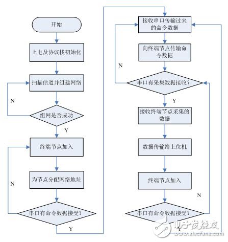
Figure 6 ZigBee Coordinator Software Flow Chart
4.3 PC application software design
The system PC application software is written in Visual Basic language, which is a structured, modular, object-oriented visual programming language developed by Microsoft Corporation that includes an event-driven mechanism to assist the development environment. Figure 7 shows the PC application software interface. By using the upper computer application software to issue command data to the electronic tag, the reading of the electronic tag ID information, the modification of the signal transmission power, and the switching of the working state can be realized.
The source code for setting the tag transmit signal power program is as follows:
ReDim bytbyte(1)
Bytbyte(0) = 221
Bytbyte(1) = 17 - 2 * Val(Form3.Combo_rssi.Text)
Form3.MSComm1.Output = bytbyte()
Set the tag working status program source code as follows:
ReDim bytbyte(1)
Bytbyte(0) = 221
Bytbyte(1) = 17 * (Val(Form3.Combo_sta.LisTIndex) + 1)
Form3.MSComm1.Output = bytbyte()
5 test results
In order to verify the reliability and stability of the experimental results, the system was tested indoors and outdoors. The indoor test is mainly to detect the transmission distance of the system through the wall, and the outdoor test is mainly to detect the transmission distance of the system. The host computer software sends control commands to the electronic tag to change the signal transmission power of the electronic tag to achieve the farthest transmission distance of the electronic tag signal, and better achieve a balance point for reducing the power consumption and the emission distance of the electronic tag. Under the condition of signal transmission power, the emission distance of the electronic tag signal is as shown in Table 1.
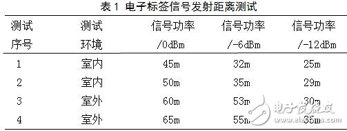
It can be seen from the test results of Table 1 that when the electronic tag signal transmission power is 0 dBm (maximum signal transmission power), the outdoor electronic tag signal transmission distance is 30-65 m, and the indoor electronic tag signal transmission distance is 25-50 m. Under the condition that the electronic tag signal transmission power is 0 dBm, the electronic tag ID numbers 1 and 2 represent the indoor and outdoor, respectively, and the test results are shown in FIG. 7.
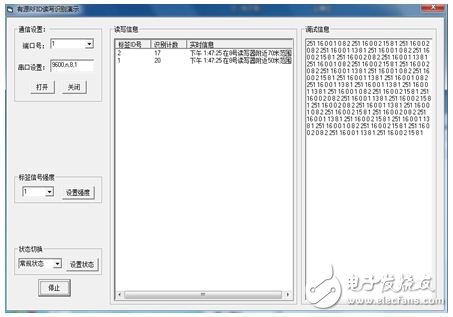
Figure 7 System test results
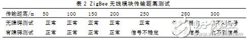
Under different indoor and outdoor conditions, the system ZigBee wireless module can effectively transmit tag data information within 200 meters, which improves the transmission distance of the system and has broad application prospects. The test results are shown in Table 2.
6 Conclusion
An electronic tag recognition system was designed through ZigBee and RFID technology. In the system hardware and software design, a low-power design method is adopted. The low-power design of the ZigBee node is realized by the microprocessor of the ZigBee node with CC2530. The nRF24LE1 is used as the electronic tag chip to reduce the power consumption and signal transmission distance. Maximize the balance point. The upper computer application software developed based on Visual Basic language can read, write and control electronic tags. Tests on the system show that under different indoor and outdoor environments and different signal transmission power conditions of electronic tags, the indoor electronic tag can penetrate the wall with a signal transmission distance of 25-50 m, and the outdoor electronic tag signal transmission distance is 30-65 m. The ZigBee wireless module based on the ZigBee protocol stack can effectively transmit data within 200 meters and improve the transmission distance of the system. At the same time, ZigBee technology networking is simple and efficient, which not only reduces power consumption and cost, but also eliminates the trouble of wiring, which makes ZigBee technology applicable in radio frequency identification, and expands the application range of ZigBee technology in wireless RFID systems.
Smt Holder
Battery Holder
Filter For Smt Machine
High Quality Smt Filter
Smt Filter
Smt Machine Filter
Smt Tape Feeder Parts
Feeder Parts For Smt Machine
Smt Machine Spare Parts
Original Smt Feeder
Original Smt Cable
Smt Machine Cable
Smt Spare Parts Fuji Cable
SMT Cable
Smt Belt
Smt Siemens Belt
Smt Juki Belt
Smt Conveyor Belt
Smt Camera
Smt Laser
Camera For Smt
Smt Siemens Camera
Smt Parts Plastic Rail
Smt Plastic Rail
Smt Juki Plastic Rail
Juki Plastic Rail
SMT Nozzle For Yamaha
Yamaha Nozzle
Nozzles For Yamaha Machine
Smt Yamaha Nozzle
Smt Siemens Nozzle
Nozzles For Siemens Machine
Smt Nozzle For Siemens
Siemens Nozzle
Smt Nozzle For Samsung
Samsung Nozzle
Nozzles For Samsung Machine
Smt Samsung Nozzle
Panasonic Nozzle
Smt Panasonic Nozzle
Smt Nozzle For Panasonics
Nozzles For Panasonic Machine
Smt Juki Nozzle
Nozzles For Juki Machine
Juki Nozzle
High Pressure Juki Nozzle
I-Pulse Nozzle
High Pressure I-Pulse Nozzle
Nozzles For I-Pulsemachine
Smt I-Pulse Nozzle
High Pressure Fuji Nozzle
Nozzles For Fuji Machine
Fuji Nozzle
Smt Fuji Nozzle
Smt Nozzle
Smt Parts Nozzle
Smt Nozzle For Machine
Smt Spare Parts Nozzle
Yamaha Smt Feeder
Yamaha Feeder
Smt Machineyamahafeeder
Smt Feeder For Yamaha
Smt Feeder For Siemens
Smt Machine Siemens Feeder
Siemens Smt Feeder
SIEMENS Feeder
Samsung Smt Feeder
Smt Machine Samsung Feeder
SAMSUNG Feeder
Smt Feeder For Samsung
Panasonic Smt Feeder
SMT Holder
Original Smt Motors
Holder For Smt Type
Smt Battery Holder
Smt Holder
Battery Holder
Filter For Smt Machine
High Quality Smt Filter
Smt Filter
Smt Machine Filter
Smt Tape Feeder Parts
Feeder Parts For Smt Machine
SMT Holder
Holder For Smt Type,Smt Holder,Battery Holder,Smt Battery Holder
Shenzhen Srisung Technology Co.,Limited , https://www.sr-smt.com