This paper describes the causes and hazards of residual current generation, designs an intelligent leakage circuit breaker, and gives the hardware structure and software design. The test results show that the intelligent circuit breaker has reliable quality and stable performance, and fully meets the requirements of national standards.
Arc-to-ground short-circuit in electrical ground faults is an important cause of electrical fires. The arc-to-ground short circuit has a large impedance and voltage drop, which limits the fault current, makes the over-current protector unable to operate or can not act in time to cut off the power supply, and the local high temperature generated by the leakage arc of several hundred milliamperes can reach 2000. Above °C, enough to ignite the surrounding combustibles and cause a fire. Moreover, the distribution of electrical equipment in all corners of the building has a wide range of hazards. If the leakage of the system is not monitored and prevented, it will pose a threat to the safety of people and property, and there is a great fire hazard. The intelligent leakage circuit breaker can accurately monitor the faults and abnormal conditions of the electric circuit, and can effectively prevent the electrical fire accidents of buildings caused by the grounding arc caused by leakage. In order to ensure the safety of people's lives and property, it is necessary to install intelligent leakage circuit breakers at the power inlet and trunk lines of buildings.
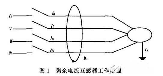
1 Reasons for residual current generation and protection principle <br> Let the three-phase four-wire wire pass through a zero-sequence current transformer CT together, or install a zero-sequence current transformer CT on the neutral line N, using these CTs Detecting the current vector sum of the three phases, that is, the residual current, as shown in Fig. 1, according to the circuit principle, when there is no equipment leakage or ground fault in the circuit and the three-phase load is completely balanced, the vector sum of the instantaneous current in the primary side is Zero, i.e., Ia + Ib + Ic + IN = 0, produces a vector sum of fluxes in the current transformer equal to zero, at which time the induced current IL = 0 in the secondary coil. When the protected circuit has an insulation fault, the load side has a ground-loaded current, and the vector sum of the zero-sequence current transformer is not zero, that is, Ia+Ib+Ic+IN≠0, and the magnetic flux is generated in the current transformer. The vector sum is also not equal to zero. At this time, the induced current is generated in the secondary winding of the zero-sequence current transformer, that is, the residual current IL≠0.
The leakage circuit breaker is mainly composed of a zero sequence current transformer CT, a leakage detection circuit and a trip unit. When the protected circuit has leakage or human body electric shock, as long as the leakage or electric current reaches the leakage current value, the secondary winding of the zero-sequence current transformer outputs a signal, which is amplified by the integrated circuit amplifier and sent to the CPU, and the CPU outputs the driving signal. The leakage release action drives the circuit breaker to trip, thereby cutting off the power supply to protect against leakage and electric shock.
2 Circuit breaker controller design 2.1 System basic function Intelligent leakage circuit breaker integrates monitoring, analysis, alarm and control of residual current, short circuit, overload, over voltage and under voltage (phase loss), etc. Features:
1) With residual current detection and protection function, when the leakage current is detected, that is, the residual current IL≠0, the signal is quickly judged after sampling by the single-chip microcomputer. When the residual current reaches the setting action value, the thyristor is driven to turn on the electromagnetic The trip unit power supply, the electromagnetic trip unit pulls in, and the circuit breaker is tripped to achieve the function of leakage protection.
2) Protection action current and breaking time adjustable: When used as total protection of the station area, the residual current action value can be set to 300~1000mA, the breaking time can be set to 0.6s, and as the secondary protection, the action current can be set to 200mA file, the breaking time can be set to 0.3s. This setting can avoid the occurrence of large-scale power outage caused by over-level tripping.
3) Intelligent identification of residual current and slowly varying residual current to identify equipment leakage and live electric shock. It is an effective technical measure for rural safe electricity use to distinguish the characteristics of the rural low-voltage power grid and the wide-ranging application.
4) It has three-stage protection function of over-current long delay, short-current short-delay and short-circuit instantaneous protection, which constitutes the required protection characteristics of intelligent leakage circuit breaker. Intelligent setting of leakage current, overcurrent long delay, overcurrent short delay and overcurrent transient setting and warning value.
5) Display and store the line address, fault type, fault occurrence time, leakage current, and three-phase current value of the fault occurrence point. Up to 200 historical faults can be recorded and saved for long periods of time until they are deleted with instructions.
6) Using RS485 bus communication technology, the bus and the host can be used to form a master-slave monitoring system to realize user network connection. On one computer, 1 to 250 intelligent circuit breakers can be remotely monitored online, and the safety of each user can be checked at any time. In any case, the power supply lines of each user can be turned on or off at any time, and various parameters of the circuit breaker can be remotely set.
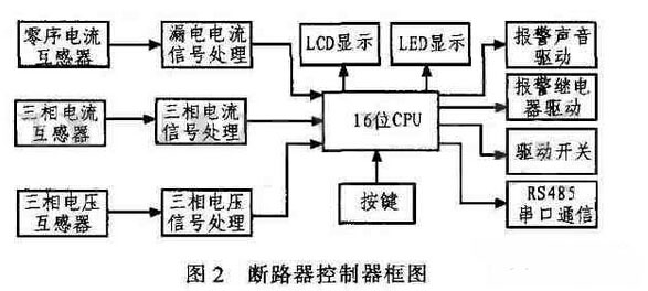
2.2 Overall hardware design Intelligent leakage circuit breaker is mainly composed of power supply circuit, single chip PIC24FJ64, three-phase AC voltage and current detection circuit, residual current detection circuit, serial communication interface circuit, human-machine interface circuit and alarm, etc. Figure 2 shows.
Its main working principle: after the three-phase current, leakage and voltage signals obtained from the current transformer and the linear optical isolator are conditioned, input to the A/D conversion of the single-chip microcomputer, and the single-chip microcomputer samples it and analyzes it, and outputs the corresponding Display and alarm signals, etc. The result of the analysis can also be transmitted to the host computer via the RS485 bus.
2.2.1 Single-chip microcomputer The single-chip microcomputer adopts PIC24FJ64, which is a high-performance CPU of improved Harvard architecture designed by Microchip. It is the core of intelligent circuit breaker. It completes various control functions of intelligent circuit breaker, including three-phase voltage. Three-phase current and leakage current sampling, data processing, alarm output, communication with the host computer, liquid crystal display and buttons. Microchip's ability to develop, develop, and manufacture microcontroller technology has the following advantages: 1) Harvard bus architecture; 2) reduced instruction set (RISC) technology; 3) simple addressing; 4) high code compression; 5) high speed; 6) Power consumption is extremely low; 7) PIC16F877 chip has A/D, MSSP, USART serial bus port, etc., and has external circuit is simple, easy to develop, C language programming, program confidentiality and so on.
2.2.2 Residual current detection circuit The residual current detection circuit is a zero-sequence current transformer. The protected phase line and neutral line pass through the toroidal core to form the primary coil of the transformer. The winding wound on the toroidal core forms the secondary coil of the transformer. If no leakage occurs, then the phase line flows. The current vector sum of the neutral line is equal to zero, so the corresponding induced electromotive force cannot be generated on the secondary coil. If a leakage occurs, the current vector of the phase line and the neutral line is not equal to zero, so that the induced electromotive force is generated on the secondary coil, and this signal is sent to the intermediate link for further processing, as shown in FIG.
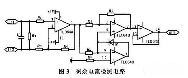
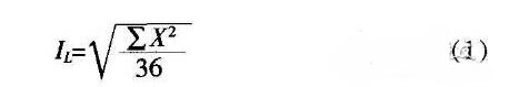
After the AC signal is processed by the absolute value amplifying circuit, full-wave rectification is obtained, and the processed signal is sent to the single chip microcomputer. The MCU samples 36 points per cycle, and the effective value of the residual current can be calculated according to Equation (1), where X is the sampled value.
2.2.3 Three-phase voltage and current and phase sequence detection Current detection consists of two three-phase AC transformers, operational amplifiers and rectifier filter circuits. The three-phase AC transformer converts the current into a voltage signal, and the circuit formed by the operational amplifier is conditioned and rectified and filtered to be input to the A/D converter of the single chip microcomputer for conversion.
The traditional voltage detection method uses a voltage transformer or a linear optical isolator. The disadvantage of using a voltage transformer for voltage detection is that the transformer is bulky. In many cases, the designed product requires a small size of the controller, so that the installation and use are convenient. The disadvantage of using linear optical isolation is that the voltage detection accuracy is not high. The system uses the current transformer and the resistor in series to detect the voltage, which greatly reduces the volume of the controller and ensures the high precision of the voltage detection. The schematic diagram is shown in Figure 4.
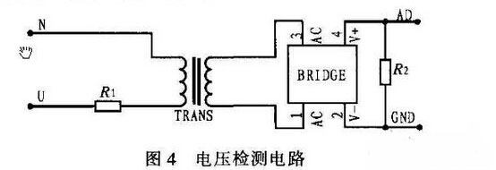
The current transformer adopts the 1:1 current transformer TV16 produced by Yaohua Electronics. Since the primary and secondary sides of the current transformer are equal, the secondary voltage is equal to the primary voltage. By selecting the appropriate resistor R1, the peak value of the output voltage of the secondary side of the current transformer does not exceed the maximum allowable sampling voltage. The secondary voltage of the transformer becomes a single-phase full-wave after passing through the rectifier bridge. The A/D converter of the single-chip microcomputer can be fully The wave is sampled and analyzed.
The power phase sequence detection adopts the peak detection method, and the phases of the three-phase voltages of A, B, and C differ by 120°. The detection method is that when the maximum value of the phase A is detected, the timing is started, and when the maximum value of the phase B is detected, the timing is stopped, and the time interval between the peaks of the two phases of A and B can be obtained, and is set to Δt, according to △. t can find the phase difference φ of the two phases A and B, and the calculation formula is:
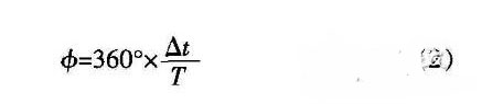
If the calculated phase difference is 110° ≤ φ ≤ 130°, the phase sequence is considered normal, and if it exceeds this range, it is determined that the phase sequence is wrong.
2.2.4 RS485 bus hardware circuit Intelligent leakage circuit breaker and host computer use RS485 bus communication, one host can control up to 250 circuit breakers, RS485 communication system adopts master-slave structure, slaves do not actively send commands or data, Everything is controlled by the host. Therefore, in a communication system, only one upper computer is used as the host, and the other slaves cannot communicate with each other, and even if there is information exchange, it must be forwarded through the host. The hardware circuit for communication with the host computer is shown in Figure 5.
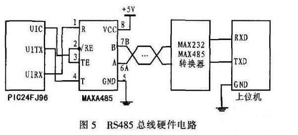
The communication between the intelligent circuit breaker and the host computer adopts the Modbus communication protocol. The Modbus communication protocol is one of the mainstream communication protocols commonly used by international intelligent instruments. The master-slave communication mode is adopted between the two. When the host computer sends a communication command to the circuit breaker, the slave device that meets the corresponding address code receives the communication command, and reads the information according to the function code and related requirements. If the CRC is correct, the corresponding task is executed and the execution result is returned to the host.
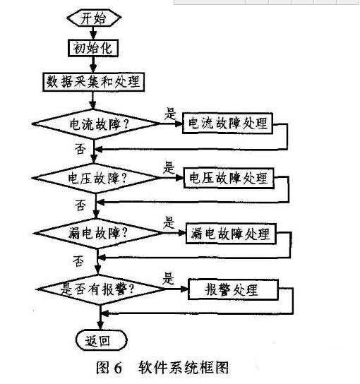
3 Software design of intelligent circuit breaker <br> The software completes the function of the whole circuit breaker, adopting modularized C language programming scheme. Mainly included procedures:
1) System main program. Mainly complete the initialization of the system's port, timer, A / D converter and other modules, and complete the LCD interface display work.
2) The timer interrupt service subroutine and the A/D conversion subroutine mainly complete the A/D conversion task and the button processing function. The MCU needs to sample 36 times in one cycle (20ms) and save the sample summer vacation.
3) The data processing subroutine mainly performs the calculation of the leakage current, the judgment of the leakage current, and the processing of the trip or not.
4) The button processing subroutine mainly provides a man-machine dialogue channel. The user can set the leakage protection setting value, delay trip time, etc. through the button, and the parameter modification has password protection.
The main software system block diagram is shown in Figure 6.
4 Conclusion <br> Intelligent leakage circuit breaker IRCCB is a kind of low-voltage electrical appliance widely used in distribution network. It is mainly used to prevent personal electric shock and equipment leakage fault. The correctness of its work directly affects the safety and reliability of power supply. The intelligent design of the intelligent leakage circuit breaker is carried out by the PIC single-chip microcomputer, which has reliable quality and strong anti-interference ability, and can realize the systemization and networking of the circuit breaker control through the application of the bus communication technology.
0 times
Window._bd_share_config = { "common": { "bdSnsKey": {}, "bdText": "", "bdMini": "2", "bdMiniList": false, "bdPic": "", "bdStyle": " 0", "bdSize": "24" }, "share": {}, "image": { "viewList": ["qzone", "tsina", "tqq", "renren", "weixin"], "viewText": "Share to:", "viewSize": "16" }, "selectShare": { "bdContainerClass": null, "bdSelectMiniList": ["qzone", "tsina", "tqq", "renren" , "weixin"] } }; with (document) 0[(getElementsByTagName('head')[0] || body).appendChild(createElement('script')).src = 'http://bdimg.share. Baidu.com/static/api/js/share.js?v=89860593.js?cdnversion=' + ~(-new Date() / 36e5)];
BLPS laser safety protective device is designed for personal safety used on hydraulic bender.
The dynamic test technology it used has passed the Type 4 functional safety assessment by TUV, and get the national invention patent. The product reaches the advanced technological level of similar products.
BLPS laser safety device provides protection zone near the die tip of the bender to protect fingers and arms of the operator in close to the upper mold die tip. It is the most effective solution so far to preserves the safety and productivity of the bender.
Press Brake Protection
Press Brake Protection,Laser Guarding Device,Press Brake Guarding Systems,Press Brake Guarding
Jining KeLi Photoelectronic Industrial Co.,Ltd , https://www.sdkelien.com