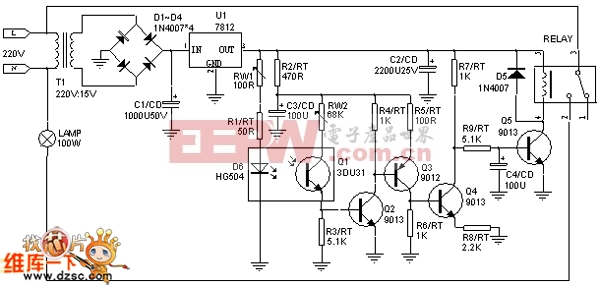
First, the working principle
When the power is turned on, the infrared light-emitting diode D6 starts emitting infrared light. This light illuminates the photosensitive transistor Q1, which enters a low-resistance state. As a result, the base of Q2 is pulled to a high level, causing Q2 to turn on. This in turn activates Q3 and Q4. However, when Q4 is conducting, the base of Q5 is held at a low level, keeping it off, so the relay remains inactive.
When a person or object blocks the infrared beam from D6, Q1 stops receiving the infrared light. This causes the collector-emitter junction of Q1 to go into a high-impedance state. As a result, Q2, Q3, and Q4 turn off, allowing Q5 to activate. This turns on the relay, which then powers the bulb.
Once the person leaves, the infrared beam from D6 resumes illumination of Q1. This brings Q1 back into conduction, turning on Q2, Q3, and Q4 again. At this point, C4 begins to discharge, and after a short delay, Q5 turns off. The relay de-energizes, and the bulb turns off.
Second, component selection
For the infrared LED D6, the HG504 model is recommended. It operates at a current of 200mA with an optical output power of 40–50mW, allowing a control range of up to about 8 meters. If the required control distance is less than 5 meters, the HG410 series can also be used. The phototransistor Q1 can be either 3DU31 or 3DU5, both of which are suitable for this application.
Third, circuit setup and adjustment
After assembling the circuit correctly, it's time to perform the initial testing. First, disconnect the base of Q4 from the circuit. Adjust the variable resistor RW1 so that the current through D6 is approximately 150mA. Ensure that Q6 and Q1 are positioned close to each other. At this point, Q2 and Q3 should be conducting.
Next, adjust RW1 so that the voltage across R1 is close to the supply voltage. Then slowly increase the distance between D6 and Q1. Depending on the width of the area you're controlling, make sure that D6 is aligned with Q1. During this process, Q2 and Q3 should remain in the on state. If they don't, you can slightly increase the current in D6, but never exceeding 200mA.
You can also adjust the resistance of RW2 to help turn on Q2 and Q3 more reliably. Once everything is stable, reconnect Q4 to the circuit. Test by blocking the infrared beam between D6 and Q1. At this point, Q5 should turn on, and the relay should activate. This completes the basic debugging process.
Fiber Optic Splice Closure
Fiber Optic Splice Closure,Fiber Optic Splice Case,Fiber Splice Closures,Outdoor Fiber Optic Splice Closure
Cixi Dani Plastic Products Co.,Ltd , https://www.danifiberoptic.com