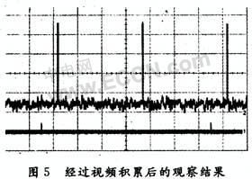
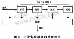
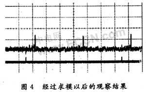
Realization of Radar Video Accumulation Algorithm on FPGA 1 Introduction Due to the complexity of the environment in which the radar is located, in addition to interference from ground features, cloud rain, and bird flocks, it may also come from nearby radar asynchronous interference and radio interference. All interference enters the signal processor through the receiver. Although it has been processed by the intermediate frequency signal, there may be residuals. Therefore, in order to get better detection performance, it is necessary to perform a video accumulation before detection. Although the effect of video accumulation is not as good as coherent accumulation, the engineering implementation of video accumulation is relatively simple. There is no strict coherence requirement for the radar transceiver system, and for most moving targets, the fluctuation of the echo will obviously destroy the adjacent The phase of the echo signal is coherent, so video accumulation is still used in many practical engineering applications. In the process of engineering implementation of the radar video accumulation algorithm, the radar signal processor is required to have fast real-time performance, and strict requirements are also placed on the stability, volume, and power consumption of the signal processor. In recent years, with the rapid development of FPGA technology, it provides us with a better way to solve this problem. Due to the arithmetic structure of the parallel structure of FPGA itself, FPGA is particularly suitable for use as a high-performance data path processor. Using FPGA to realize radar video accumulation algorithm has the advantages of real-time strength, small hardware system, flexible structure, suitable for modular design, short development period, and support for online programming, making the system have strong universality and scalability. Taking this as the starting point, this paper proposes and discusses a method of FPGA video accumulation using FPGA technology. 2 System hardware structure In the specific implementation process, a FPGA-based core signal processing card is mainly used. It can not only collect the intermediate frequency and video signals from the radar receiver and perform digital signal processing on it, but also can generate the intermediate frequency and video signals of the radar to perform digital signal simulation. Send it to the radar signal processor with or without processing. The block diagram of the hardware circuit structure of the radar signal processing card is shown in Figure 1. FPGA uses Xilinx's 1 million gate FPGA chip XC3S1000, and its configuration chip is Xilinx's 1 Mb capacity PROM chip XC18V01, which powers on the FPGA in active serial mode. AD, DA are ADI's 12-bit high-speed analog-to-digital conversion chip AD9432 and 14-bit high-speed digital-to-analog conversion chip AD9764SRAM using Cypress's 256 k × 16 b SRAM chip CYTC1041. In the design, FPGA is used to realize the PCI interface logic of 32 b / 33 MHz, real-time signal acquisition and transmission control. Since FPGA has a hierarchical memory system, its basic logic function blocks can be configured as 16 × 1, 16 × 2 or 32 × 1 synchronous RAM, or 16 × 1 dual-port synchronous RAM, so high-speed dual The port RAM is used as a data buffer for signal transmission. At the same time, in order to save the internal logic resources of FPGA, an appropriate SRAM is configured on the periphery of the FPGA to store data. 3 Realization of video accumulation algorithm on FPGA There are usually many ways to realize the engineering of video accumulation. In terms of time domain, video accumulation is to superimpose the video echo signals of units of the same distance in consecutive N repetition periods, so the burst line cannot be separated from the delay line. When using FPGA to realize digital delay line, it is necessary to quantize and store the signals of the previous N-1 cycles, which requires a large amount of storage and calculation. Therefore, in actual engineering, a sliding window detector is often used for the occasion where the number of echo pulses N is received when the antenna beam sweeps over the target, but if the value of N is still large, the sliding window detector still needs Storage capacity. Therefore, when using FPGA to realize video accumulation, using a small sliding window detector is more suitable for the characteristics of FPGA. The small sliding window detector is a detector in which the window length L (the accumulated pulse number is L) is less than the number N of echo pulses received when the antenna beam sweeps over the target. L is generally much smaller than N, for example, N is above 10-20, and L takes 5-7. The principle block diagram of small sliding window detection method for video accumulation is shown in Figure 2. Clk in Figure 3 is the system main clock; count_dist is the distance counter; acc_en is the enable signal for video accumulation, and acc_en is valid when it is high; count_dist, clk and acc_en are the main system variables that control the timing relationship; acc_data is after the modulo The input non-coherent signal, the system video signal is continuously input into FPGA in real time. The FPGA quantizes the acc_data signal into RAM_data signal through timing control; when the read signal RAM_we of RAM is high, RAM_data is written into the SRAM address, and the previous L-1 cycle quantization signal is stored in the high-speed SRAM through timing control, After the signal is full in SRAM, RAM_rd is high; when RAM_we is low, the first L-1 signals stored on the same distance unit in SRAM are read out through timing control and input with the current The signal is accumulated in the FPGA to complete the detection of a small sliding window with a window length of L, thereby achieving video accumulation of non-coherent video signals. 4 Simulation verification In order to verify the principle of this article and the realization effect of this system, first simulate to generate the coherent video signal after modulo in radar signal processing, the signal only contains amplitude information and clutter (according to the parameter setting, it is generated directly in the FPGA chip by software programming ), Video accumulation of the analog signal is sent to the oscilloscope for display after D / A conversion. Download the compiled and integrated BIT file to the FPGA chip for system joint debugging, and finally view the simulation results on the oscilloscope. Figure 4 is a screenshot of the radar coherent video signal after modulo on the oscilloscope. The clutter of the signal is approximately uniformly distributed with an average value of 0; Figure 5 is a screenshot of the oscilloscope after video accumulation of the analog signal . 5 Conclusion This article focuses on the principle and process of video accumulation using FPGA chips. Using FPGA to accumulate radar video can make the system more flexible, reduce the size of the system, improve the reliability of the system, and greatly shorten the cycle of system development. With the update and rapid development of FPGA chips and design update software, FPGA chips will have the ability to repeat complex calculations at a higher speed, and at the same time have the flexibility of software, and can reuse hardware to reduce costs, blurring the hardware and software The boundary between them makes the hardware system more flexible and versatile. In the end, this paper uses FPGA software programming to simulate a radar coherent video signal after modulo simulation, and uses this system to accumulate video for this signal, and achieved good results. Thin Load Cell,Thin Film Load Cell,Thin Beam Load Cell,Low Profile Load Cell Xiaogan Yueneng Electronic Technology Co., Ltd. , https://www.xgsensor.com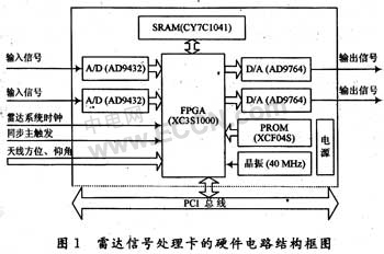
In this design, FPGA + SRAM is used to realize video accumulation through FPGA software programming. The delay of the small sliding window detector is mainly accomplished by quantizing the signal and storing it in a high-speed SRAM. The schematic diagram of FPGA software programming to realize video accumulation is shown in Figure 3. 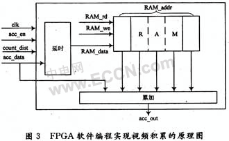
It can be seen from the results of the simulation that using this system to perform video accumulation on the signal after the modulo has achieved an ideal effect. 