I. Introduction This article refers to the address: http:// Since the 1980s, with the widespread use of integrated circuits and microcontrollers in automobiles, there are more and more electronic control units on automobiles, such as electronic fuel injection devices, anti-lock braking devices (ABS), airbag devices, Electronically controlled door and window devices and active suspensions, etc. In this case, if the conventional wiring method is still used, that is, one end of the wire is connected to the switch and the other end is connected to the electric device, the number of wires on the car will increase sharply, so that the quality of the wire accounts for the mass of the whole vehicle. %about. In addition, although the increase of the electronic control system improves the power, economy and comfort of the car, the complicated circuit that is added also reduces the reliability of the car and increases the difficulty of maintenance. To this end, the call for reform of automotive electrical technology is growing. Therefore, a new concept - the car controller area network CAN came into being. CAN is the abbreviation of Controller Area Network, which was developed by Bosch and several semiconductor manufacturers in Germany. CAN bus is a serial multi-master controller LAN bus. It has high network security, communication reliability and real-time performance, and is simple and practical, and the network cost is low. It is especially suitable for automotive computer control systems and industrial environments with harsh ambient temperatures, strong electromagnetic radiation and high vibration. Second, the technical characteristics of CAN bus The CAN bus can effectively support distributed control or real-time control. The communication medium of the bus can be twisted pair, coaxial cable or optical fiber, and its main features are as follows: Third, the CAN control design of the body system 1. CAN bus network system architecture The control unit of modern automobile pawn has engine control module, transmission control module, multimedia control module, airbag control module, air conditioning control module, cruise control module, body control module (including lighting instructions and window, wiper, etc.), defense Locked brake system (ABS) anti-skid control system (ASR). The perfect car CAN bus network system architecture is shown in Figure 1. 2. Hardware architecture of the CAN node In this system, the CAN node adopts: The circuit structure of ECU (AT89C51) + CAN controller (SJA1000) + CAN transceiver (PCA82C250) is the following is a summary of its core chip: (1) CAN controller In order to further expand the system, a chip SJA1000 supporting the CAN 2.0B communication protocol can be selected. The SJA1000 is a CAN controller manufactured by PHILIPS that supports both CAN 2.0B and CAN 2.0A. It is fully compatible with the CAN controller PCA82C200, which only supports CAN 2.0A, in hardware and software. (2) CAN transceiver The PCA82C250 is a CAN controller and physical bus interface chip from PHILIPS that provides differential transmission and reception of the bus. It is fully compatible with the ISO 11898 standard and has three different modes of operation: high speed, slope control and standby, which can be selected according to the actual situation. (3) Single-chip AT89C51 The AT89C51 is a microcontroller from ATMEL. It is a low power, high performance, 8-bit CMOS microcontroller with 4KB of flash memory and is fully compatible with the industry standard MCS-51 command system and pins. The superiority of the AT89 series is that its on-chip flash memory can be programmed and erased 1000 times, and the data is not easily lost, and the data can be stored for 10 years. The basic method of CAN bus controller, bus driver and single chip connection is shown in Figure 2. Third, the CAN application layer protocol in the body control module 1. Principle of agreement This protocol follows the CAN2.0B specification. According to the characteristics of the body control module, the source→purpose method is adopted. Each node has its own fixed identification address, and the number of nodes is less than 64. The central control module can be set as the master node during design. The door, the electric seat sub-module and the self-test sub-module are set as slave nodes. This agreement can complete the following functions: (1) Broadcasting of specific information; This protocol uses the frame first principle to assign identifiers. The upper four bits of each frame identifier indicate the frame type. Different frame types have different priorities. The priority determines the order in which various information frames are transmitted under the same conditions. The assignment of the 29-bit identifier in is as follows: Frame type (4 bits) + destination address (6 bits) + source address (6 bits) + command (or status, report) attribute (13 bits) [or data attribute + segment flag + segment number (13 bits total) ]. In principle, all commands or status, data, report attributes, and data collected in addition to the timing are required to be acknowledged (send an acknowledgement frame to ensure normal communication). 2. Frame format arbitration field and control field definition The arbitration field consists of a 29-bit identifier ID28-ID0 and SRR, IDE and RTR. Registers 17-21 in SJA1000 are used to store the identifier of the extended frame format frame information. When transmitting, SRR=1, IDE=1, RTR=1/0 (remote frame/data frame). ID28-ID25 in the identifier is the frame type (4 digits in total) of the body control module exchange message. ID24-ID19 is the address of the frame information user (or the destination address, a total of 6 bits) in the body control module. ID18-ID13 is the address of the sender of the frame information in the body control module or called the source address (a total of 6 bits). ID12-ID5 is the command, status, data or report attribute (8 bits in total) exchanged in the body control module. The ID4 bit needs to be appended with a command or status, data, and segmentation flag when reporting attributes. ID3-ID0 is the segment number (4 digits in total) of the additional command or status, data, and report attributes. When ID4=0, the ID3-ID0 control field and data register 0-7 are valid. For remote frames, ID4-ID0 and the value of the control field can be ignored. The lower four bits of DLC3-DLC0 of register 16 of SJA1000 can form a control field to determine the data length of the data frame. 3. Body control module CAN2.0B communication message convention According to the node requirements of the body control module, the communication information frames are divided into six types listed in Table 1. The priority levels in Table 1 are arranged from high to low according to the serial number. The allocation of destination address and source address is listed in Table 2. Table 1 Body Control Module Frame Model Table 2 Address assignment of each node of the body control module It works as follows: (1) After power-on or wake-up, the slave node sends status information to the master node, and the master node transmits a broadcast information remote frame (twice), and the broadcast information is shared information, including a vehicle speed signal, a gear position signal, an ignition switch position signal, and the like. (2) Under normal circumstances, the status of each port is patrolled from the inside of the node. If there is a fault, the fault code is sent to the master node three times. After the master node receives three fault alarms, it starts to respond, and the slave node stops transmitting. Once the fault disappears, The master node sends normal information. There should be a fault table in the master node for communication with the diagnostic module. (3) After the main node sends the self-test information separately, if the slave nodes are normal, the normal information, status and data frame are sent. If there is a fault, the fault alarm frame is sent through the segmented data frame. (4) After monitoring from the node to the change of the normal input signal (including the change of the switching quantity and the analog sampling stage), the information is sent to the primary node through the report frame, and the primary node sends the command frame to indicate the response. 4. Communication message definition Table 3 lists the communication message definitions of the central control module and the diagnostic module. In the table, aaaa is a segment number, which can be set when there are more than 8 fault codes, and can transmit up to 16×8 byte codes; bbbbbb is each sensor code, and the response frame adopts non-segmented data frames, cccccccc The code for executing the corresponding action, such as the window rising to 00000001, is reduced to 00000010, and the response can perform up to 256 actions. The response frame uses a remote frame and the request frame is a remote frame. Table 3 Communication between the central control module and the diagnostic module Table 4 Communication protocol agreement of each node during normal operation When the system works normally, the communication protocol conventions of each node are listed in Table 4. The dddd in the table is the total number of segments included in the segment start command; eeee is a segment number of the broadcast information, the data length in the control field is the data length in the segment, and the actual data of a certain segment of the data broadcast in the data field , the data defined in order has: Fourth, the software process Each controller shall send data to the bus in the specified format and cycle, and also accept information from other controllers. The other controllers on the bus take the required messages as needed. For receiving data, the system is implemented in an interrupt mode. Once the interrupt occurs, the data to be received is automatically loaded into the corresponding message register. At this time, the mask filtering method can also be adopted, and the identifier of the received message and the identifier set in advance when the receiving buffer is initialized by the mask filter register can be used. The characters are selectively compared bit by bit, and only the packets whose identifiers match can enter the receiving buffer, and those that do not meet the requirements will be shielded from the receiving buffer, thereby reducing the burden on the CPU to process the message. In addition, different data should be placed in different message registers. Therefore, in the receiving interrupt service program, it can be easily judged which receiving message is caused by the interrupt, and the program flow chart is shown in FIG. V. Conclusion As a reliable car calculator network bus, CAN bus has been applied in advanced cars, enabling each car computer control unit to share all information and resources through the CAN bus to simplify wiring and reduce the number of sensors. Avoiding the duplication of control functions, improving system reliability and maintainability, reducing costs, better matching and coordinating the purpose of each control system, so that the power, operation stability and completeness of the car are raised to new heights. With the development of automotive electronics technology, CAN bus communication protocol with high flexibility, simple scalability, excellent anti-interference and error correction capability will be more widely used in automotive capacitor systems.
These keywords represent critical components and applications within the electrical and industrial sector. Here's how they can be classified:
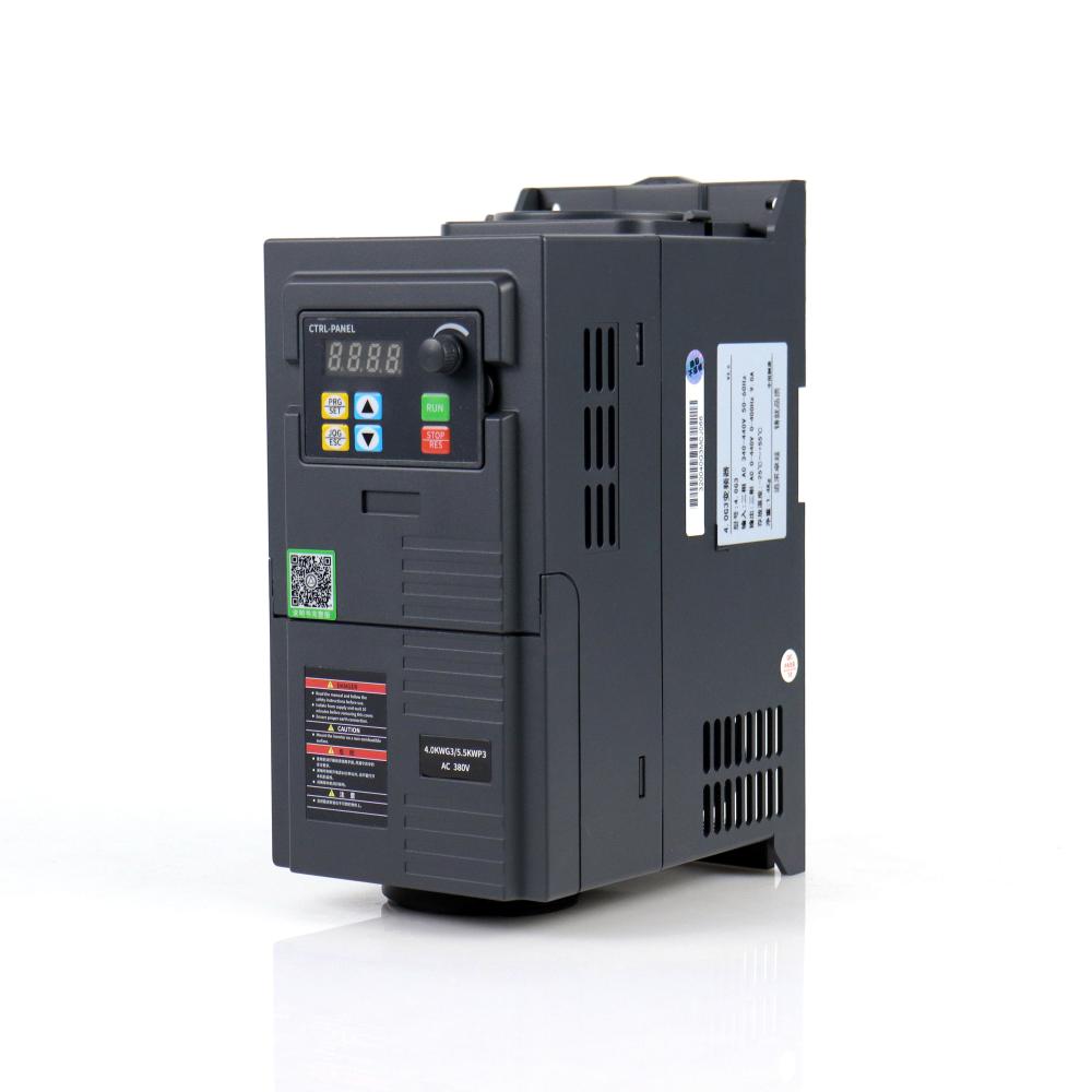
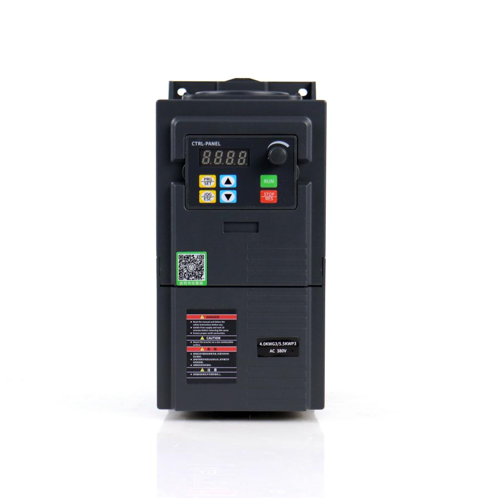
Frequency Converter: A frequency converter is a device that converts the frequency of an alternating current (AC) to match the requirement of a particular electrical device or system. This allows equipment designed for specific frequency to operate in regions where the electrical supply has a different frequency. For example, a frequency converter can be used to allow a device designed for a 60Hz supply to operate in a region with a 50Hz supply.
Variable Frequency Drive (VFD): A VFD is a type of motor controller that drives an electric motor by varying the frequency and voltage of its power supply. VFDs have significant applications in industrial systems and machinery, where they allow for precise control of motor speed and torque, leading to increased efficiency and longevity of equipment.
Pumps, Fans, Conveyors: These are common applications of motors controlled by VFDs. The variable speed provided by the VFD allows these systems to operate more efficiently and adjust to the specific demands of their task. For instance, a pump's flow can be controlled more accurately, fans can be speed adjusted according to the cooling requirement, and conveyor speed can be precisely managed based on the production line's needs.
Phase Motor: A phase motor refers to the type of electric motor, which operates based on the phase of the power supply. The most common types are single-phase motors and three-phase motors. Single-phase motors are usually found in lower power applications like household appliances, while three-phase motors are used in higher power applications, often in industrial settings. These motors can be controlled using VFDs for enhanced performance and efficiency.
These components play significant roles in various industries and are essential for efficient operation in many modern systems. The use of VFDs and phase motors, in particular, has revolutionized the way we control and optimize industrial processes, leading to substantial improvements in energy efficiency and system longevity.
Frequency Converter,Variable Frequency Drive,Pumps Fans Conveyors,Phase Motor WuXi Spread Electrical Co.,LTD , https://www.vfdspread.com
Figure 1 Automotive CAN bus network system architecture 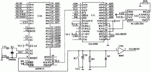
Figure 2 CAN bus controller, bus driver and microcontroller connection diagram
(2) the connection between the master and slave nodes;
(3) Information exchange between the master and slave nodes (including fault information). 
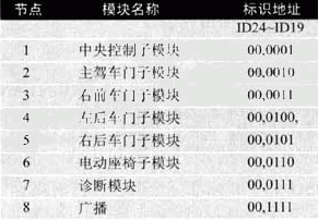

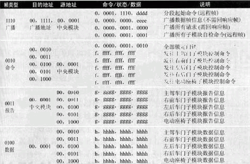
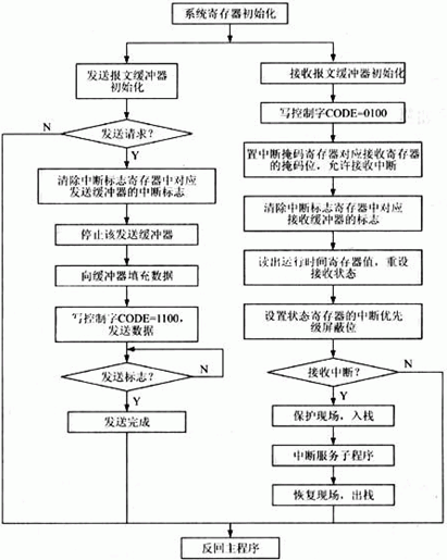
Figure 3 program flow diagram
