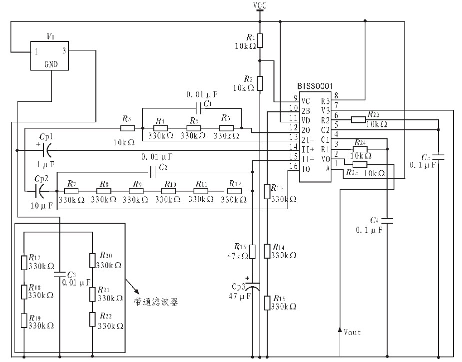
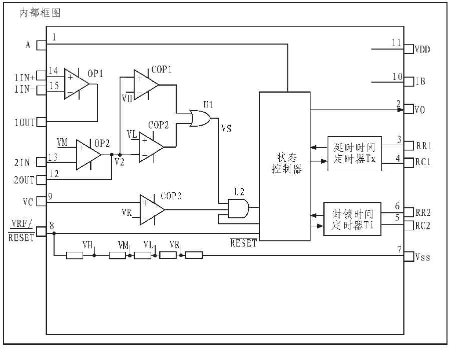
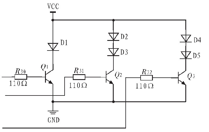
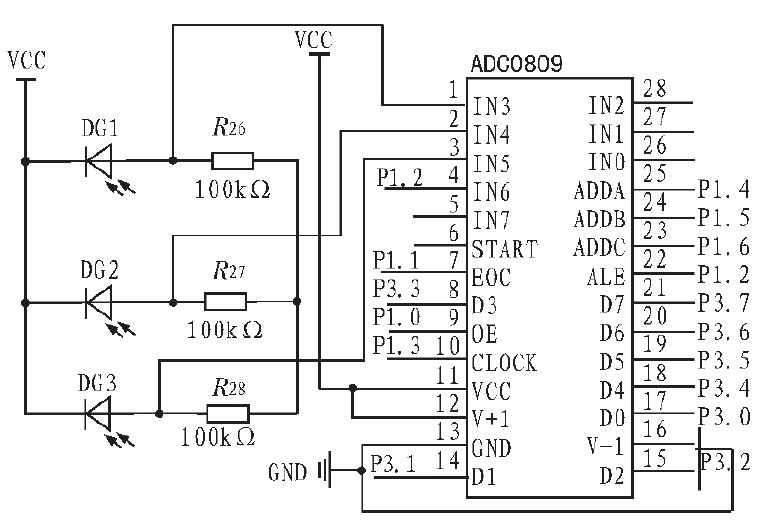
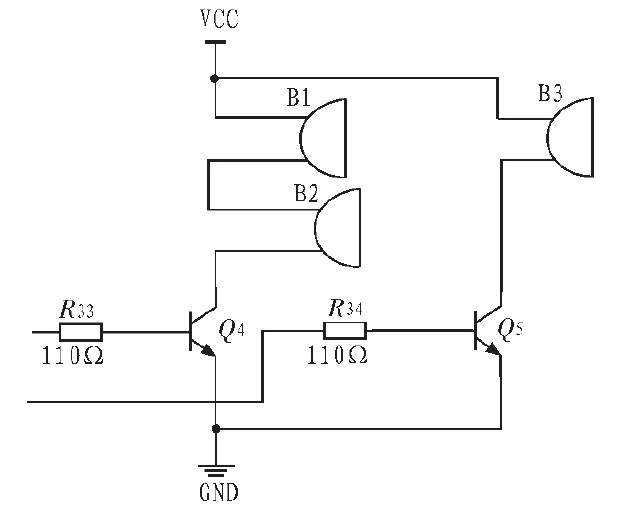
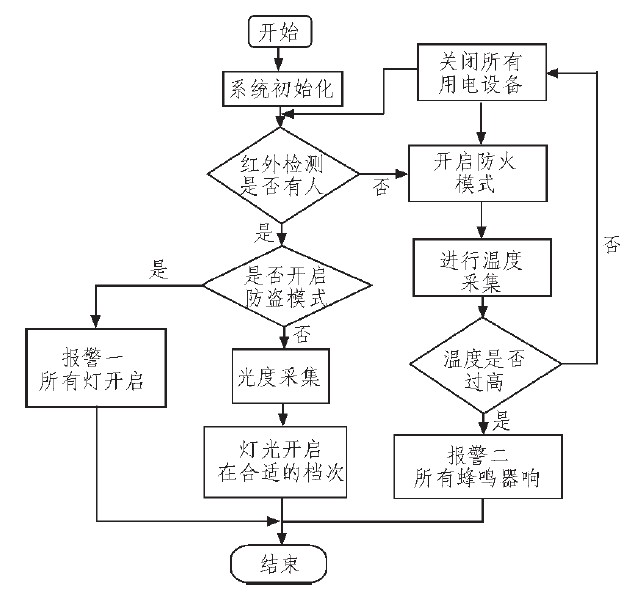
Abstract: This system uses a single-chip microcomputer as the controller to detect the presence or absence of personnel and indoor temperature in the room by using the thermal release human body infrared and temperature sensing system. An intelligent anti-theft fire prevention and lighting control system is designed. The system can alarm in real time according to the temperature in the room to prevent the fire from happening; and according to the light in the room and whether there is someone to control the lighting of the lamp; use the buzzer as the alarm source, if the alarm mode is activated, when the area is detected Someone will send out an alarm signal and start a long beep when the temperature exceeds a certain range. It can achieve intelligent control, energy saving and security purposes, especially for school classrooms, libraries, corridor lighting places. With the rapid development of the economy and the progress of society, the time for people to travel and work outside is gradually increasing. When the public places such as homes, shopping malls, computer rooms or laboratories are empty, the most worrying issue may be security issues, such as whether There will be thieves breaking into the door, whether it is caused by various power lines due to prolonged use, etc.; and now most of the lights are manually operated by people, especially when we go home in the middle of the night. When the lights are insufficient or the lights are turned on manually when going up the stairs, this will bring us a lot of inconvenience. In addition, the waste of electricity is often caused by the negligence of the staff member who forgets to turn off the equipment after the person leaves. In order to solve the above problems, in the design of the system, consider using the single-chip microcomputer as the main controller, using the pyroelectric body infrared module, the temperature sensing system and the photodiode to detect the presence of indoors and indoors, thereby controlling the indoor lighting. The degree of brightness and darkness, and when the temperature exceeds the alarm and timely alarm, the overall design of an intelligent anti-theft fire and lighting control system, real-time adjustment and control of indoor lighting, so as to achieve intelligent control, energy saving and anti-theft and fire prevention purposes. 1 Principle and design 1.1 System overall design In the design of this system, the single-chip microcomputer is used as the main controller to detect the presence or absence of personnel and indoor temperature in the room by using the thermal release human body infrared and temperature sensing system. Another intelligent anti-theft fire control system is designed, and the photodiode is used to detect the indoor Light intensity, real-time adjustment and control of indoor lighting, to achieve intelligent control and energy saving purposes. According to the system design requirements and considering the feasibility of the system, the design block diagram of the whole system is shown in Figure 1. The system takes the single-chip microcomputer as the main controller, and controls the human body sensing module, the temperature collecting module, the photometric collecting module, the light pipe brightness module and the alarm module respectively. The 51 MCU and the pyroelectric body infrared are used to detect whether there is any person in the area. If someone checks whether the illuminance needs light and realizes which position is adjusted, the indicator position is displayed by the indicator light. Finally, the buzzer is used as the alarm source. If the alarm mode is activated, an alarm will be sent when someone detects that it is in the area. When the temperature exceeds a certain range, a long beep will sound. Figure 1 system block diagram The basic working principle of the intelligent anti-theft fire prevention and lighting control system is that when the alarm mode is not activated, when a person in the room is detected, the photometric acquisition module is turned on, and the LED lamps of different grades are respectively turned on according to the indoor light intensity; if the indoor temperature is too high, The alarm device will send a second alarm to prevent the fire from happening; when someone enters the room and turn on the alarm device, if the person or the staff can cancel the alarm through an invisible manual reset button, if someone enters the room, the first level alarm will be turned on. And all the LED lights are on, which plays the role of timely alarm and anti-theft. 1.2 system hardware design The hardware design of the system is divided into five large modules, namely the heat release human body infrared module temperature acquisition module, the photometric acquisition module, the LED light display module and the alarm module. The hardware design and basic working principle of each module are respectively introduced below. 2 experiment 2.1 Thermal release body infrared module The human body infrared sensing module circuit is mainly composed of a human body infrared sensor, a Fresnel lens and a special chip BISS0001. When someone appears in its detection zone, the sensor can detect the signal and transmit the signal to the microcontroller. The microcontroller then turns on the device or allows the electrical equipment in the room to be turned on according to the actual situation. In addition, regarding the corridor and the hand-washing lamp, when someone passes by at night, the human body infra-red senses the person to turn on the corridor lamp or the bathroom lamp. The pyroelectric body infrared module circuit is shown in Figure 2. Figure 2 Thermal release human body infrared circuit diagram A special thermal infrared chip BISS0001 is used in the circuit. It is a digital-analog hybrid ASIC consisting of an operational amplifier, a voltage comparator, a state control, a delay time timer, and a lock-up timer. The internal circuit is shown in Figure 3. When the infrared radiation radiated by the human body is focused on the detector element of the pyroelectric infrared sensor through the Fresnel lens, the sensor in the circuit will output a voltage signal, and then the signal is first passed through a band pass filter, the upper limit of the filter The cutoff frequency is 16 Hz and the lower cutoff frequency is 0.16 Hz. Figure 3 BISS0001 chip internal circuit diagram Because the pyroelectric infrared sensor output detection signal voltage is very weak (usually only about 1 mV), and is a changing signal, and the Fresnel lens makes the output signal voltage pulsed (pulse voltage is 0.1 ~) The voltage signal output from the pyroelectric infrared sensor should be amplified by the operational amplifiers OP1 and OP2 for secondary amplification. After processing by the two-way amplitude detector formed by the voltage comparators COP1 and COP2, the valid trigger signal Vs is detected to start the delay time timer. The output signal Vo is connected to the single-chip microcomputer for detection. When there is a person, it outputs a high level of 5 V. When the person leaves, after a delay, it is reset to 0 V for the control of the main control circuit. The circuit design puts the chip in a repeatable trigger state to suit the actual situation in the classroom. Repeatedly triggering its working process: In the repeatable trigger mode, when Vc=“1†and A=“1â€, Vs can repeatedly trigger Vo to be in an active state, and can cause Vo to remain valid for a period of Tx. During the Tx time, as long as Vs jumps up, the % will continue to extend from the time of the Vs transition to a Tx period; if Vs remains in the "1" state, then Vo remains active; if Vs remains " In the 0" state, Vo returns to the inactive state after the end of the Tx period, and also during the blocking time Ti, any change in Vs cannot trigger Vo to be in an active state. 2.2 Temperature Acquisition Module Using the P2.5 port of the MCU to control the DSl8B20, compare the temperature collected in real time with the value set by the MCU software, and control the conduction and cut-off of the triode with P2.3 and P2.4 ports, realizing the buzzer at high temperature. The time of the alarm request. The DS18B20 temperature sensor used here is a single-line digital temperature sensor chip manufactured by Dallas. It is different from the traditional thermistor. The DSl8B20 can directly convert the measured temperature into a serial digital signal [9] for processing by the microcontroller. . 9 to 12-bit temperature readings can be achieved by programming the DSl8B20, and 9-bit and 12-bit digital quantities can be completed in 93.75 ms and 750 ms, respectively. The temperature range is -55 to +125 °C, the maximum resolution is 0.062 5 °C, and the temperature accuracy is ±0.5 °C in the range of -10 to +85 °C. DS18B20 has the characteristics of small size, low power consumption, strong anti-interference ability, easy connection with microprocessor, and it can easily measure temperature without any peripheral hardware. Only one I/O line is needed to exchange information with MCU. The power of reading and writing and temperature conversion is also available on the data bus. Its circuit connection diagram is shown in Figure 4. Figure 4 temperature acquisition circuit diagram 2.3 Photometric acquisition module This module is mainly composed of photosensitive sensing circuit, digital-to-analog conversion module and indoor LED lamp. Here a photodiode and a 100 kΩ resistor are used for the simulation. A total of 5 groups are connected in parallel to connect 5 V voltage, and 5 lines are connected to the ADC3809 chip. The IN3~IN7 channel circuit connection is shown in Figure 5. The brightness of the classroom is detected by the photodiode. The resistance value will be significantly reduced. As the luminosity decreases, the resistance of the photodiode will gradually increase. Then the different voltage values ​​(ie, analog quantities) obtained by the partial voltage division of each photodiode are detected by ADC0809 analog-to-digital conversion. The amount of analog they output. The IN3~IN7 ports of the ADC0809 chip are converted into digital quantities, and D0~D7 are used as data output ports, which are connected to the P0 port of the MCU for data processing. Figure 5 Photometric acquisition circuit diagram In the simulation, the lamp is replaced by LED lamp, and the brightness of the lamp is divided into 3 gears (according to the best luminosity, which does not affect the eyes of the person): 1st gear: When the room is full of light, turn on the LED light, and the brightness of the room light is the lowest. 2nd gear: When the indoor light is not enough, the first two rows of three LED lamps are turned on at the same time. At this time, the indoor lamp brightness is moderate. 3 files: At this time, it is detected that the indoor light is obviously insufficient, and all the LED tubes are turned on at this time, and the brightness of the indoor tube is large at this time. 2.4 LED light display module The LED light display module is mainly composed of three-level LED lamps. The P2.0, P2.1 and P2.2 ports are used to control the conduction and cut-off of the triode, which realizes the response to different requirements of the input terminal. LED0, LED1 in the system, LED2 is the photometric control input port of the first gear, the second gear and the third gear respectively. Its hardware circuit diagram is shown in Figure 6. Figure 6 LED light display circuit diagram 2.5 alarm module During the simulation, the module uses two NPN transistors as the buzzer respectively. When the b pole is high, the triode is turned on, and the buzzer works to make a sound. When b is extremely low, the triode does not conduct and the buzzer does not work. The b pole is connected to an invisible manual switch for the start and stop switching of the alarm mode. The alarm sound is controlled by the P2.3 and P2.4 ports of the single-chip microcomputer. When a thief invades, the buzzer emits a continuous alarm sound. When the temperature is too high or a fire occurs, the buzzer sounds to alert the staff. Its hardware connection circuit is shown in Figure 7. Figure 7 alarm circuit diagram Of course, in practical applications, the buzzer's alarm sound can not meet the requirements, and other high-power alarm devices can be used, such as high-power alarm bells, etc. can meet the requirements. 3 system software design The software system is divided into photometric acquisition module, human body sensing module, temperature acquisition module, LED light display module and alarm module. The main process of the software design of the system is shown in Figure 8. Figure 8 software flow chart The specific program design has been basically completed, because the code is more than this, it will not be repeated. 4 Conclusion In this design, the AT89C51 single-chip microcomputer is used as the controller. The thermal release human body infrared, photodiode and temperature sensing system are used to detect the presence or absence of indoors, the indoor light intensity and the indoor temperature, and an intelligent anti-theft fire prevention and lighting control system is designed. The system can control the lighting of the lamp according to the light in the room and whether there is someone; use the buzzer as the alarm source. If the alarm mode is activated, an alarm will be sent when someone detects the area, and the temperature will start when the temperature exceeds a certain range. Long sounds an alarm. It can achieve intelligent control, energy saving and security purposes, especially for school classrooms, libraries, corridor lighting places. This design completes the hardware simulation and programming of the system by making PCB circuit and using PROTEUS software and KeilC software. The system simulation debugging has passed, the basic functions of the system can be fully realized, and can be put into practical use through the improvement of circuit devices.
we offer a wide selection of Traffic Steel Pole structures in standard and custom designs.
Yixing Futao Metal Structural Unit Co. Ltd. is com manded of Jiangsu Futao Group.
Traffic Signal Pole, Traffic Light Pole, Led Traffic Signals, Solar Traffic Signal Pole,Traffic Steel Pole YIXING FUTAO METAL COMPONENT UNIT CO.,LTD , http://www.chinasteelpole.com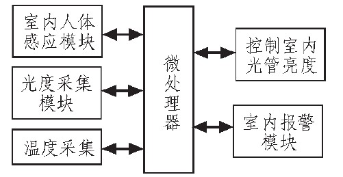
0 times
Window._bd_share_config = { "common": { "bdSnsKey": {}, "bdText": "", "bdMini": "2", "bdMiniList": false, "bdPic": "", "bdStyle": " 0", "bdSize": "24" }, "share": {}, "image": { "viewList": ["qzone", "tsina", "tqq", "renren", "weixin"], "viewText": "Share to:", "viewSize": "16" }, "selectShare": { "bdContainerClass": null, "bdSelectMiniList": ["qzone", "tsina", "tqq", "renren" , "weixin"] } }; with (document) 0[(getElementsByTagName('head')[0] || body).appendChild(createElement('script')).src = 'http://bdimg.share. Baidu.com/static/api/js/share.js?v=89860593.js?cdnversion=' + ~(-new Date() / 36e5)];
It is located in the beach of scenic and rich Taihu Yixing with good transport service.
The company is well equipped with advanced manufacturing facilities.
We own a large-sized numerical control hydraulic pressure folding machine with once folding length 16,000mm and the thickness 2-25mm.
We also equipped with a series of numerical control conveyor systems of flattening, cutting, folding and auto-welding, we could manufacture all kinds of steel poles and steel towers.
Our main products: high & medium mast lighting, road lighting, power poles, sight lamps, courtyard lamps, lawn lamps, traffic signal poles, monitor poles, microwave communication poles, etc. Our manufacturing process has been ISO9001 certified and we were honored with the title of the AAA grade certificate of goodwill"
Presently 95% of our products are far exported to Europe, America, Middle East, and Southeast Asia, and have enjoyed great reputation from our customers,
So we know the demand of different countries and different customers.
We are greatly honored to invite you to visit our factory and cheerfully look forward to cooperating with you.