The ADV611 chip is a codec/decoder chip produced by the American ANALOG DEVICES company that uses the wavelet algorithm to perform real-time compression/decompression processing of video images. The chip not only integrates the video encoding/decoding algorithm, but also provides real-time adjustment of the data compression effect, and the data output rate can be flexibly controlled. This paper introduces an offline video encoding/decoding system based on ADV611 chip and TI chip DSP chip TMS320C542. The offline video encoding/decoding system is designed to remotely control the image acquisition front end by the user at the far end of the image playback. At the image playback end, the user sends a control command to the microcontroller B through the controller, and then these commands are sent to the DSP.A of the image acquisition front end via the DSP.B and the communication device. DSP.A divides control commands into two categories. The first type is the image brightness, contrast, color saturation adjustment command and camera focal length, pan/tilt movement adjustment command, DSP.A notifies the single-chip A, and finally the single-chip A controls the video A/D chip and the camera completes the command. Another type of command is a command to adjust the image frame rate and wavelet image processing effect. DSP.A directly sets the relevant register implementation command of ADV611.A. DSP.A calculates the control parameters of the ADV611.A image compression coding effect on the acquisition side in the main program. The ADV611 provides the user with three means of controlling image effects and data flow through the control registers. The first one is to set the quantization coefficient, that is, to change the quantization weight of each different frequency band data after wavelet decomposition, to achieve the purpose of data compression. The second compression method is frame subtraction, and the ADV611 can be reduced from 50 frames/second to 2 frames/second. The last compression method is quality box control. The ADV611 can set a display area in one frame of 720&TImes; 288 and attenuate the image outside the area, thereby compressing the data by using the method of reducing the effective frame size. . The size of this display area is set by adjusting the internal quality box data of the ADV611. In the main program, DSP.A will calculate and modify the control register parameters in ADV611.A according to the user's adjustment command.
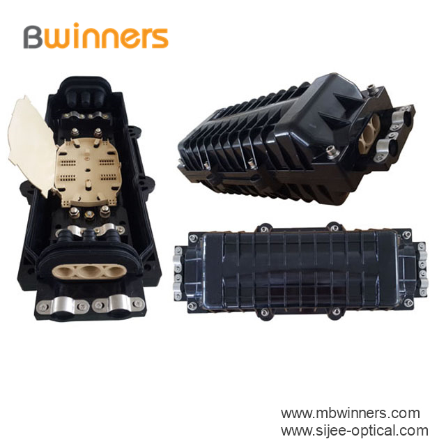
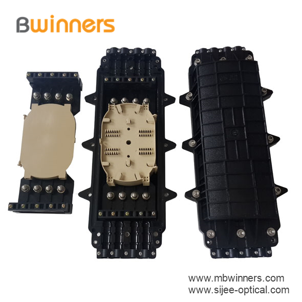
Fiber optic splice closures are made of excellent engineering plastics. Sijee supply different ports types, fittings and different fiber optic core numbers for horizontal and dome fiber optic splice closures.
Sijee's Splice Closure is suitable for protecting optical fiber splices in straight through and branching applications, and can be used in aerial, duct and direct buried fiber optic cable projects.
Horizontal Fiber Optic Splice Closure Horizontal Fiber Optic Splice Closure,New Horizontal Fiber Optic Splice Closure Sijee Optical Communication Technology Co.,Ltd , https://www.sijee-optical.com
In this offline video image encoding/decoding system, DSP is used as the control core. On the one hand, it is necessary to manage ADV611, memory, peripheral control MCU and communication interface. On the other hand, it is necessary to adjust the image compression effect of ADV611 and control the data rate in real time. . How DSP can efficiently perform these control tasks is the key to the implementation of this video encoding/decoding system. Because TMS320C542 has high-speed computing power and rich interface resources, it is a high-speed microprocessor that integrates data processing and communication functions. Therefore, the DSP of this system chooses TMS320C542.
1 overall system structure
Figure 1 shows the overall structure of the system block diagram. In Figure 1, the original PAL system (720 × 288 @ 50 frames / sec) video signal is converted into CCIR656 format (8-bit 27MHz) data stream through the image acquisition end of the video A / D, and then wavelet compression by ADV611.A coding. DSP.A reads out the image data from ADV611.A and buffers it in the data memory. According to the rate of the communication device, DSP.A transmits the compressed encoded image data to the image playback terminal through the communication device via the communication serial interface. After the DSP.B of the image playback terminal receives the data from the serial interface, it is buffered in the memory, and then the compressed video data is sent to the ADV611.B according to the data request of the ADV611.B. The image data recovered by ADV611.B is still sent to the video D/A as a video analog signal in the standard format of CCIR656, and finally played back by the monitor. 
2 DSP and video wavelet encoding/decoding chip ADV611
In the image acquisition end and image playback end of the system, the ADV611 is connected to the address data bus of the DSP chip as an I/O port device of the TMS320C542. Through this interface, the DSP can read and write the internal control registers of the ADV611, and can read and write image compression data to the ADV611. The control registers inside the ADV611 contain three types. The first type is used to set the working state of the ADV 611, including image encoding status, image decoding status, and image processing system. The second type of registers provide statistics for each frame of image. They are read-only registers and provide statistics such as the maximum, minimum, and sum of the brightness and the amount of compressed data per frame of image. The last type of register is the control register for data encoding and compression. The internal FIFO of ADV611 is used to control the read and write operations of image compressed data, and can give FIFO full-empty, partial full and full-full signals.
All ADV611 processing request signals including image compression data access request, statistical data ready for each frame, and data stream error share an interrupt request to the DSP. Figure 2 shows the processing flow after the DSP.A response interrupt is taken as an example of the image acquisition end. DSP.A first reads the interrupt flag register inside ADV611.A, and further analyzes the cause of the interrupt, and then processes it. Since the processing of the image compression data takes a long time, in order to prevent the ADV611.A new processing request from being missed during the image data processing, the DSP.A reads the ADV611 interrupt flag again after reading the encoded data and writing it to the memory. register. 
      Â


Fiber Optical Splice Closure