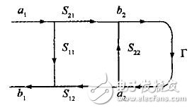
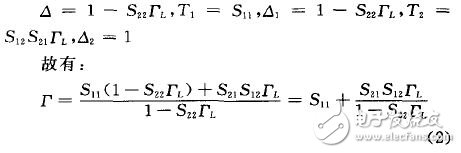
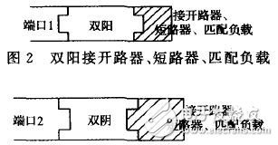
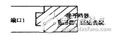
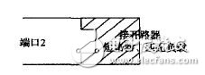
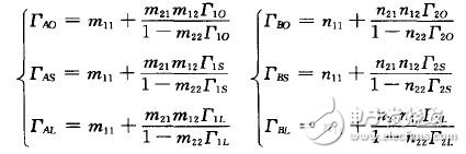
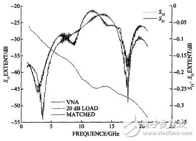
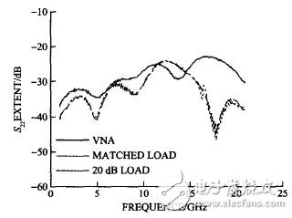
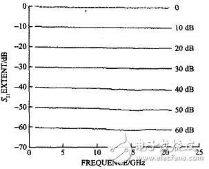
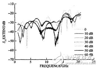
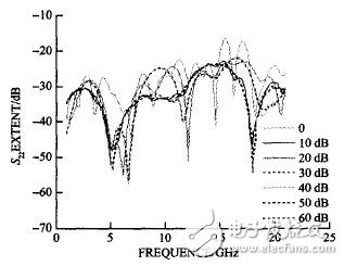
Due to the needs of microwave engineering, most of the ports of the microwave RF components are female, while the ports of the cable connecting devices are a yin and a yang. These microwave RF components cannot be directly connected to the vector network analyzer for straight-through testing. It is a non-intrusive device. In the actual measurement, there are a large number of non-inserted devices, their port connection types are reversed, the anode and cathode are the same, and the straight-through measurement cannot be directly performed during calibration. In order to connect the non-intrusive device to the vector network analyzer, a double or double male adapter must be added, so that the test value of the vector network analyzer is not the actual value of the device under test, but the value of the device under test plus the adapter. . In the general measurement, the influence of the adapter is neglected. It is considered that the measured result is the actual value of the measured component, and the loss and delay of the adapter are invisibly added to the device to be tested, so that the accurate value of the device to be tested cannot be obtained. . Or different calibration methods are used in the test, for example, the characteristic is not determined by the straight-through method, the characteristic determination straight-through method, the adapter exchange method, the adapter removal, etc., to reduce the influence of the adapter on the device under test, but these methods are good or bad. The effect of the adapter on non-inserted devices cannot be removed directly. In this paper, the adapters with unknown characteristics (such as double-yang and double-female connectors) are tested by single port. According to the algorithm and assumptions, the theoretical calculation value after cascading is close to the actual measured value, and then the value of the adapter is determined, and finally the measured value is obtained. The exact value of the piece, thereby removing the effect of the adapter on the device under test. 1 principle The signal flow diagram (shown in Figure 1) combined with the scattering parameters is a simple and effective method for analyzing microwave networks and microwave measurement systems. The flow graph formula is also known as the Mason's non-touching loop rule, referred to as the Mason formula. According to the Mason formula, the transmission value between any two points in the signal flow graph can be directly obtained. Figure 1 signal flow Mason formula: According to the Mason formula: 2 verification process There are many kinds of adapters. For the convenience of research and universality, this test is verified by double yin and double yang. The principle and process of other types of adapters are the same. In the experiment, one set of vector network analyzer (100 MHz to 40 GHz), two cables, and 2.4 mm calibration parts (AV31123, calibration parts and cables with high precision and small error) are used. One step attenuator. Set the linear frequency range from 1 to 21 GHz, taking one point per 100 MHz, scanning points 201, and IF bandwidth 100 Hz. After the two-port cable is connected to the vector network analyzer, after the cable is fully dual-port SOLT calibrated, the cable port is the calibration end face, and 12 system errors are removed. After the preparation is completed, use different methods to test. In method 1, the double negative and double positive values ​​are calculated by connecting 50Ω matching load; in method 2, the double negative and double positive values ​​are calculated by connecting programmable step attenuators. The following is a detailed process of the two methods. 2.1 Method 1 After port 1 is connected to the double male connector, the open circuit breaker, the short circuiter, and the 50 Ω matched load (as shown in Figure 2) are respectively measured to have reflection coefficients of ΓAO, ΓAS, ΓAL. After port 2 is connected to the double female connector, it is connected to the opener, the short circuiter, and the 50Ω matching load (as shown in Figure 3). The measured reflection coefficients are ΓBO, ΓBS, ΓBL, respectively. Then port 1 is directly added to the opener, short circuit, 50 Ω matching load, and the reflection coefficients are measured as Γ1O, Γ1S, Γ1L (as shown in Figure 4). Port 2 is directly added to the opener and short circuiter, and the measured reflection coefficients are Γ2O, Γ2S, Γ2L (as shown in Figure 5). Figure 3 Double cathode opener, short circuit, matching load Figure 4 Port 5 is connected to the opener, short circuit, matching load Figure 5 Port 2 is connected to the opener, short circuit, matching load From equation (2), the equations [SA] and [SB] of the double-yang and double-yin can be obtained as follows: Where: m11, m12, m21, m22 are the parameter values ​​of the double male joint to be tested, and n11, n12, n21, and n22 are the S parameter values ​​of the double female joint. Assuming that the network reciprocity is, m12 = m21 n12 = n21, the equations can solve the double-positive S-parameter matrix SA and the double-sinus S-parameter matrix SB. They are: 2.2 Method 2 Using a 2O dB attenuator as the load replacement method for the 50 Ω matched load, the vector network analyzer is used to measure the reflection coefficient ΓAL, ΓBL of the attenuator connection double cathode and double anode, and the reflection coefficient of the 2O dB attenuator is Γ 1L. , Γ 2L. The other steps are similar to Method 1. Calculate S and compare it with Method 1. 3 verification For the feasibility of the above method, the calculated values ​​of the double-yang double-negative joint were verified by two methods. 3.1 Cascade Shuangyang Double Yin First calculate the S parameters after the double-yin and double-yang cascade. The S-parameter of the cascaded two-port network cannot be directly calculated. It is necessary to convert the S-parameter to the T-parameter, find the cascaded value [TAB] - [TA][TB], and then convert the cascaded [TAB] to [ SAB]. Shuangyang double yin cascade (as shown in Figure 6). Figure 6 Shuangyang double yin cascade The S parameters obtained by the above method are reference values, and these values ​​are compared with the S parameters calculated by the Mason formula. All test data were processed by MATLAB software, and the S-parameter curve after final cascading was compared with the S-parameter curve tested in the vector network analyzer. It can be seen from Fig. 7 that the difference between S12 and S21 is small, but there are some differences between S11 and S22. The two curves of the 50 Ω matched load in Method 1 and the 20 dB attenuator in Method 2 are basically the same. After the double-yang double-yin cascade, regardless of the load, the cascaded value is fixed. The reason for the difference is that the 20 dB attenuator is not a standard device, and there is reflection in the double-yang double-cascade cascade. Figure 7 S11, S22 tested by Shuangyang double-yin connection 20 dB attenuator and vector network analyzer test The graph of the theoretical calculation of S11 is very close to the test curve of the vector network analyzer. In the low frequency band, the curve of the theoretical calculation value of S22 is consistent with the test curve of the vector network analyzer. The theoretically calculated value at high frequencies is better because the reflection coefficient is below -40 dB and the isolation is high. In fact, the connection port of Shuangyang Double Yin was affected during the straight-through test. Therefore the theoretical calculation is more accurate than the measured value. In the test, there are multiple connections to the standard parts, the adapter and the attenuator, and each connection will cause human error to varying degrees. The value of the standard part is obtained by calibration after the calibration of the vector network, and no higher-level calibration system test is used. The measurement of the transmission parameters is indispensable for obtaining the s-parameters, but in the experiment, only a variety of factors of the transmission parameters are indirectly obtained by measuring the reflection coefficient, and there must be a certain error in the result. A certain correction of these errors can lead to better results. 3.2 Programmable Step Attenuator The following verification uses a programmable step attenuator with attenuator attenuation values ​​of 0, 10 dB, 20 dB, 30 dB, 40 dB, 50 dB, 60 dB, respectively. The S parameters of the attenuator are calculated from experimental data (as shown in Figures 8-10). Figure 8 S21 theoretical value of the attenuator Figure 9 S11 theoretical value of the attenuator Figure 10 S22 theoretical value of the attenuator It can be seen from the above calculation results that the S-parameter of the programmable step attenuator calculated without the double-yang double-yin joint is obtained with the expected result. The calculated value of the attenuator is verified to match the transmission parameters and reflection parameters given by Agilent. 4 Conclusion This paper is a confirmatory experiment that removes the effects of non-insertion devices on the test by calculating the double and double anode adapters. The problem of universal adapters has been specialized and simplified, but this has made a theoretical breakthrough in the measurement of other adapters and further research on port extension and de-embedding techniques.
LEDER technology`s ceiling light takes fashion design, more stereoscopic than other flat ceiling lights. Ideal luminous output for indoor use,step-less dimming, white light, warm light, neutral light, three bright modes are available. Perfect for balcony, bar, cafe, clothing store, aisle, etc.
This flush mount edge-lit LED technology of the ceiling light channels the light to the side of the fixture and then redirects it downwards, creating a uniform light distribution without hot spots, flicker or glare.Station it in the dining room above a rectangular table to find just the right light at your next casual dinner gathering, or hang it up over the entryway to put a spotlight on the foyer as guests walk in.
Features:
• Fashion design
• Easy to install
• Incandescent, and CFL
• Energy saving electricity
• Product Type: Semi flush mount
• Color temperature :3000k-6000K
• Sloped ceiling compatible
• Type of protection: IP20 /IP65 (Some models)
• Warranty:3 - 5 years
LED ceiling lights are an especially good choice for anyone looking for a Lamp which is elegant in an understated way. If you want a lamp that discreetly keeps itself out of the way, yet looks great once you actually pay attention to the ceiling light, you have definitely come to the right place. This ceiling light will do its job very well.
We have rich production experience in lighting. Except LED Ceiling Light, we also offered other product in Indoor Lighting .Such as : LED Downlight , LED Panel Light, Track Light , Linear Light , LED Strip Light , LED Tube Light , LED Bulb , as so on .
LED Ceiling Light Bedroom Ceiling Lights,Bathroom Ceiling Lights,Home Depot Ceiling Lights,Semi Flush Ceiling Lights JIANGMEN LEDERLIGHT LIGHTING Co.,LTD , https://www.wallwasherlights.com