Current output type transmitter signal wiring method - Database & Sql Blog Articles

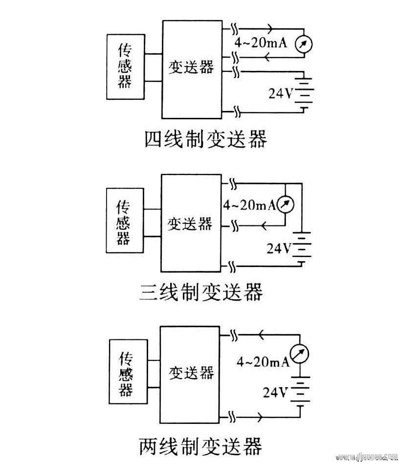
In the power system, current output transmitters typically use four-wire, three-wire, or two-wire signal wiring configurations, as illustrated in the diagram below.

Signal wiring diagram

Signal wiring diagram

A current output transmitter converts physical quantities into a 4–20 mA current signal, which requires an external power supply. The most common configuration is the four-wire transmitter, where two wires are used for power and two for the current output. This setup ensures accurate signal transmission but increases cabling complexity. In a three-wire transmitter, one of the current lines can be shared with the power supply (either VCC or GND), reducing the total number of wires to three. This simplifies installation while maintaining performance. The two-wire transmitter is the most advanced design, where the 4–20 mA current itself powers the transmitter. In this case, the transmitter acts as a load in the loop, drawing current between 4 and 20 mA depending on the measured value. This configuration only needs two wires, making it highly cost-effective and efficient. The 4 mA lower limit of the industrial standard ensures that the transmitter always has enough power to operate, even under low signal conditions. This feature makes the two-wire system not only feasible but also highly reliable in various applications. Two-wire transmitters offer several key advantages: 1) They are less affected by parasitic thermocouples, voltage drops, and temperature drift along the wire. Thin and inexpensive cables can be used, significantly reducing cabling costs and installation efforts. 2) When the current source has high output resistance, magnetic field coupling induces minimal interference. Twisted pair cables help reduce noise further, while shielded cables are required for three-wire systems, and proper grounding is essential. 3) Capacitive interference can cause errors in the receiver’s resistance. However, in a 4–20 mA two-wire loop, the receiver resistor is usually around 250 Ω, producing a small voltage drop (1–5 V). This minimizes error and allows longer wire runs compared to voltage-based telemetry systems. 4) Each measurement device can switch between different channels without losing accuracy due to varying cable lengths. This enables decentralized data acquisition and centralized control. 5) Using 4 mA as the zero level makes it easy to detect open circuits, short circuits, or sensor failures, as a 0 mA signal indicates a fault. 6) Surge protection devices can be easily added at the two-wire output port, improving safety against lightning strikes and electrical surges. Compared to three-wire and four-wire transmitters, two-wire systems are more compact, cost-effective, and robust. As a result, they are gradually replacing older technologies in many industries. With the increasing demand for reliable, long-distance signal transmission in harsh environments, two-wire transmitters have become the preferred choice. Field devices often require monitoring from remote locations, sometimes tens or hundreds of meters away. These environments are prone to electromagnetic interference and lightning-induced surges, making signal integrity a critical concern. The two-wire transmitter provides a solution that ensures stable and accurate signal transmission over long distances, even in challenging conditions. Its simplicity, reliability, and cost-efficiency make it a vital component in modern industrial automation and control systems.

Step Up Transformer

Step Up Transformer,High Frequency Transformer,Step Up-Down Voltage Converters,Electronic Switching Power Supply Transformer

Huizhou Show-Grand Electronics Co., Ltd. , https://www.sgtransformer.com