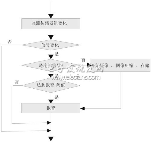
introduction This article refers to the address: http:// The popularity of automobiles has brought convenience to people's lives, and it has also raised a big problem for people - car anti-theft. This design is a car anti-theft alarm system integrated with three major functional modules of sensing, alarm and remote image monitoring developed to solve the shortcomings and shortcomings of previous car anti-theft products. System working principle and composition The system is to install the sensor in the hidden position of the vehicle body. When someone walks into the monitoring distance, the body moves or vibrates, and the door is opened, the sensor sends an electric signal and sends it to the main controller through the A/D conversion device. According to the source of the signal, the controller divides the alarm into three levels: “someone is closeâ€, “body vibration†and “door is openedâ€, and the GPRS/GSM terminal sends the alarm information to the user's mobile phone by SMS. The "door is opened" as a high-level alarm, notify the user at the same time, start the video driver, record the live inside the car through the camera inside the car, and send it to the owner's mobile phone. In the first two cases, the system does not transmit images unless the client actively views the image. At this time, the system hardly occupies the channel. When an intruder enters the defense zone, the MCU sends an alarm message to the user through the mobile phone short message. Since only the text information is sent at this time, the amount of information is small, and the information transmission speed is fast. At the same time, the system stores the screen at the time of the alarm in the storage device in the system for the user to view. System hardware design Overall framework of the system The hardware of the system consists of the following modules: main controller module, information acquisition module (sensor), USB camera module, wireless communication module (GPRS MODEM) and image compression module. Main control module Samsung's S3C2410 is based on the ARM core, and its maximum operating frequency can reach 203MHz. It can support NAND flash booting and has higher cost performance. In addition, the S3C2410 has many mature applications in the market, so the S3C2410 is selected as the CPU of the system. The S3C410 integrates an LCD controller (supports STN and TFT LCD), NAND flash controller, SDRAM controller, 3-channel UART, 4-channel DMA, 4 PWM-enabled timers and 1 internal Clock, and 8-channel 10-bit ADC. The S3C2410 also has a wealth of external interfaces, such as touch screen, I2C bus, 12S bus interface, and 2 US host interfaces, 1 USB device interface, 2 SPI interfaces, and SD interfaces. On the clock side, the S3C2410 integrates a calendar-enabled RTC (real-time control) and a chip clock generator with a PLL. Can produce a working frequency of 200MHz. This frequency of operation enables the processor to easily run WinCE, Linux and other operating systems, as well as more complex data processing. USB camera The USB camera is mainly composed of three parts: lens, image sensor and USB interface control chip. The camera used in this system is a relatively common one on the market. Its USB interface control chip model is 301p, and the image sensor chip uses CMOS technology, so the cost performance is higher. The camera can communicate directly with the host via the USB interface to transfer the captured image to the host. The features of the chip are as follows: the maximum image size is 640 × 480 pixels, which can be adjusted according to different cameras; the image white balance and other parameters can be configured; it can run efficiently under the Arm-Linux embedded system; the CMOS image sensor is programmed through the I2C bus. Register to change the default parameters. Wireless communication module The system adopts GSM2406 module, which has simple interface and convenient use, and only needs a single 2.7V power supply to work. The module is controlled by the AT command, and the serial port is used for communication between the preliminary plan and the controller. At the same time, use this module to implement the voice call function. Since GPRS is based on the IP protocol, the processor sends a data packet conforming to the IP protocol when communicating with the GPRS network. Image compression module Since the video processing chip 1s outputs 25 frames of images, and a frame of 640 x 480 images is about 2.45 Mb, in order to alleviate the storage pressure of the memory, the image must be compressed to increase the access speed. The system design uses ZR36060 image compression chip with integrated JPEG codec. It can easily implement real-time compression/decompression of video signals. When compressed, the ZR36060 receives the YUV 4:2:2 digital video signal and encodes it into a JPEG stream output; when decompressed, it receives the JPEG stream and decodes it into a YUV 4:2:2 digital video signal. Output. The interface of ZR36060 is divided into three parts, namely video interface, code and host interface and control interface. The function of the video interface is to complete the input/output video signal; the function of the code and the host interface is to initialize the chip control word through the host, and in the active mode, the JPEG compressed code stream is also input/output through the CODE[7:0]. The control interface performs a series of simple work sequence control operations. The two video synchronization modes are synchronous main mode and synchronous slave mode. Synchronous master mode refers to all control and timing signals generated internally by the chip; synchronous slave mode is that the chip is synchronized as a slave to an external video source. Data acquisition module The data acquisition module of the anti-theft system is composed of a microwave Doppler sensor group, a vibration sensor group, a Hall device group and a pyroelectric infrared sensor group, and is used for collecting automobile anti-theft information and preliminary fusion processing of data. The structure of the data acquisition module is shown in Figure 1. Figure 1 Composition of the data acquisition module Using microwave Doppler sensors Monitoring the scope of the invasion The microwave Doppler sensor uses Agilis' HB100 microwave motion sensor module. The Doppler Effect Transceiver Module of the HB100 utilizes a dielectric resonant oscillator and microstrip patch antenna technology to achieve low current consumption, high temperature stability and high sensitivity. Monitoring the vibration and tilt of the vehicle body with an acceleration sensor Measuring the vibration and tilt of the car body can provide an early warning to the thief to use the towing method to steal the vehicle and damage the car body. Because the acceleration sensor ADXL202E can measure dynamic or static acceleration in the range of 0~5kHz and ±2g: the measurement of dynamic acceleration can be used for vibration detection, and the static gravity acceleration can be used as the input vector to determine the spatial direction of the object. Therefore, the vibration and tilt angle of the vehicle body can be monitored simultaneously using the ADXL202E. Using Hall switch devices Monitor the door switch The A3210E is a Hall-effect switching device. With the digital signal output, the Hall effect can be generated under the action of the north and south magnetic poles: when the magnetic pole is close, the switch is opened and the output level is low; when the magnetic pole is far away, the switch is closed and the output level is high. This type of sensor consumes very little power, such as the A3209E's low power consumption of up to 400mW, making it ideal for low-power applications. The Hall device group is designed to distribute multiple Hall devices in the four doors of the car. When the door is opened, the Hall device emits a weak electrical signal, and then the output signal of each switching device is sent to the device group. The local decision-making center is integrated. Here, the alarm levels of the four doors are regarded as the same, and the hardware can be directly ORed to obtain the fusion result and sent to the central processing module. Key technologies in design operating system Linux kernel configuration The steps to configure the Linux kernel are as follows: 1. NIC and serial port configuration The kernel image download requires serial port and network card. The serial port and network card driver must be modified to ensure successful porting. In order for the kernel to support the serial port, the following configuration options must be available for the serial port when configuring the kernel: The serial port driver is located in the source tree ///drivers/serial/amba.c, and the NIC driver is located at linux/drivers/net/ann/smc9lx.c and linux/drivers/net/arm/smc9lx.h. The memory map of the network card is simpler than the serial port. 2. USB System Configuration To enable the USB system, first enter the USB support section and enable the Support for USB option (the corresponding module is usbcore.o). Next, you need to select the USB host controller driver. The options are EHCI (corresponding module is ehci-hcd.o), UHCI (corresponding module is usb-uhci.o), and OHCI (corresponding module is usb-ohci.o). Each motherboard that supports plug-in USB devices requires a USB host controller chip. This particular chip interoperates with the USB device plugged into the system and handles all the low-level details necessary to allow the USB device to communicate with the rest of the system. Once the USB support and USB host controller drivers are enabled, the Preliminary USB devicefilesystem should be enabled and the drivers for the USB peripherals enabled. For example, to enable support for a USB camera, USB Camera support should be enabled. Once rebooted with the new kernel, there should be corresponding USB device information in the directory //proclbus/usb. If there is no information, you should manually load the USB device file into //proc/bus/usb by entering the following command. 3. Camera This car terminal uses the cam301p camera, so you should choose cam301p when configuring the Linux system kernel. Compile the new kernel After configuring the kernel, go to the /usr/src/linux-2.4.18 directory and perform the following steps: Once the kernel is compiled for the target system, the kernel is loaded into the memory of the target system by using the bootloader. By using the serial port, the boot loader communicates with the host and transfers the kernel to the target's DRAM. After the kernel is fully loaded into the target, the boot loader passes control to the kernel. Image alarm technology Image alarm is the key technology of the system, and it is also the difficulty of the system. Through the analysis and control of the monitoring image, the alarm and alarm processing are realized. The technology incorporates sensors, digital processing, imaging and image processing technologies. The alarm flow chart is shown in Figure 2. Figure 2 alarm flow chart Since the sensor is a weak signal detection device, it is easily affected by external factors and causes false alarms. Some can be avoided by the user's efforts; some are in principle unavoidable, such as small animals and electromagnetic interference. False alarm. In order to minimize the false alarm rate, the system adopts a digital processing technology, which directly digitizes the analog signal, and presets the alarm threshold on the MCU through comprehensive analysis of various intrusion situations and interference situations. The signal collected by the sensor is sent to the MCU for processing. When the alarm threshold is exceeded, the MCU starts an alarm; below the alarm threshold, it is judged as an interference signal and does not alarm. Conclusion This design uses the embedded system as the platform, combined with sensors, data acquisition, image processing and wireless communication technology to achieve remote monitoring and anti-theft function of the car, effectively reducing the false alarm of the car alarm system. In the theory and practice, the image monitoring of the car is all-weather. Due to the influence of network status, the alarm information may be delayed. With the development of network and communication technologies, it is believed that these problems will be solved perfectly.
LED outdoor
lighting fixtures are the choice for parking lot lighting for applications
including shopping malls, retail shopping plazas, sports stadiums, business
complexes, airports, and much more. Our outdoor lights provide reduced offsite
visibility, as well as effective security light levels with symmetric and
asymmetric distributions. They can yield a significant reduction in system
energy compared with standard HID systems and virtually eliminate ongoing
maintenance expenses. Whether you need commercial LED Parking Lot Lights or
commercial HID Parking Lot Lights, we have you covered.
Parking Lot Lights Parking Lot Lights,Solar Parking Lot Lights,LED Parking Lot Lights,Outdoor Parking Lot Lights Shenzhen Ri Yue Guang Hua Technology Co., Ltd. , https://www.ledlightinside.com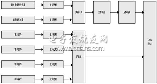
First, enter the system's source code directory /Linux-2.4.18, run the menuconfig command, the system will automatically enter the configuration interface. The interface is very intuitive. Here, you need to configure the serial port, network card and camera separately.
[*] ARM AMBA PLOT! serial port support
[*]Support for console on AMBA serial port
The following kernel configuration options are required for the NIC:
*)Ethernet (10 or 100M)
Generic Media independent Interface device support
[*]SMC 91C9x/91Clxxx support
#mount-t usbdevfs none /proc/bus/usb
Multimedia devices--->
<*>Video For Linux
Video For Linux--->
[*]V4L information in proc filesystem
USB support--->
<*>USB cam301p Camera support
1. $make dep to properly set all dependencies.
2. $make clean, clear all existing object files. If you forget to do this, the generated kernel will be very large.
3. $make zImage to generate a compressed kernel.
4. Run make modules and make modules_install.
5. make install.