Abstract: The biggest drawback of the existing home security system is that it can not effectively verify the alarm information in time, which leads to the problem of false positives and misstatements. In order to overcome this problem, the situation of the alarm scene is reflected in the form of the MMS picture on the user's mobile phone screen in time. In addition, in order to further enhance the anti-theft security of the system, a dual electronic lock is designed. The lock adopts the RFID code sensing technology and the user's unlocking time rule, effectively overcoming the phenomenon that the thief uses the universal key to unlock. The test results achieved the expected results. This article refers to the address: http://
Desktop Electronic Calculator advantage:
100% brand new and high quality Desktop Calculator;Chain and percentage calculation;
Big display, convenient for viewing;
Desktop Electronic Calculator,Desktop Calculator,Mini Electronic Calculator,Desktop Electronic Solar Calculator Dongguan City Leya Electronic Technology Co. Ltd , http://www.dgleya.com
Keywords: GPRS MMS; serial camera; dual electronic lock
0 Introduction With the rapid development of electronic technology, the alarm system has evolved from the simplification and localization to the intelligent and integrated. The main difference between various anti-theft alarm systems is how to make the extension communicate with the host, extension and user. At present, the communication methods of the common anti-theft alarm system on the market include fixed-line dialing, Ethernet, and GSM short messages. But they have their own shortcomings:
(1) Fixed-line dialing is easy for a thief to cut off a telephone line or maliciously occupy a line before burglary, causing it to fail at a critical time;
(2) Ethernet is also facing the hidden danger of the line being cut off, and it is not easy to popularize;
(3) The GSM short message alarm system does not filter the information, which causes false positives and misstatements, which brings great inconvenience to the user.
Aiming at the shortcomings of the above communication methods, a multi-function home security system based on GPRS MMS module is designed. The system solves these hidden dangers and makes the home security more timely and convenient to use. Instead of relying on wired phones to perform alarms, it relies on the most reliable and mature GPRS mobile network to directly reflect the alarm scene to your mobile phone screen in the most intuitive MMS picture and phone format. It adopts the active infrared sensor for detection, and the tangible traditional anti-theft security window is invisible, which provides convenience for escape during fire, and is equipped with a smoke sensor and a gas leakage sensor to achieve fire prevention and gas leakage prevention. In addition, in order to overcome the phenomenon that thieves use the universal key to unlock, a dual electronic code lock is designed. The electronic lock is composed of an electronic code lock of RFID code and an electronic code lock of voice prompt.
1 Basic idea of ​​design In the design process, the whole design is divided into two modules according to the design content: main control circuit module and dual electronic lock module. The two modules are controlled by the ARM chip and the Sunplus MCU.
First, the super user's number is stored in the SIM card. When the intrusion signal is detected by the sensor, the wireless module starts immediately and sends the intrusion signal to the ARM7 processor. After receiving the signal, the processor starts the serial port camera and takes a picture. After the picture signal is processed, it is sent to the super user by the GPRS MMS module, and the invading location and the triggered sensor are sent to the user in the form of short messages, so that the user can timely alarm. The main control module block diagram is shown as in Fig. 1. 
As shown in Figure 2, the electronic lock original password and user setting password are stored in the external memory E2PROM. To open the door, the user must first open the RFID code sensor lock with the electronic sensor key. When the sensor lock is successfully unlocked, the system will give a voice prompt. “Induction lock unlocked successfullyâ€, and then enter the previously set password. After the password is correct, the system will give a voice prompt “Unlock successfullyâ€, otherwise it will prompt “Enter password incorrectâ€. Enter the password more than three times and the system will alarm and lock for 30 minutes. The entire unlocking time should not exceed 30 s, otherwise the system will sound an alarm to prevent the thief from unlocking with a universal tool in a short time. When the system is in standby, it can display information such as time, date and day on the LCD to achieve a friendly man-machine interface.
2 system hardware design
2.1 Main control module circuit The main control module consists of five parts: sensor module, wireless receiving/transmitting module, serial camera module, GPRS MMS module and ARM7 processor module.
2.1.1 Sensor Module (1) Smoke Sensor This design uses ionic smoke sensor. The ion smoke sensor is a kind of advanced technology, stable and reliable sensor. It is widely used in various fire alarm systems and has excellent performance. For fire alarms in gas-sensitive resistors.
(2) Human proximity sensor The sensor can detect a range of 1 m, which can be placed on both sides of the window. When a thief breaks into the window, the sensor will trigger.
(3) Door magnetic sensor In order to prevent illegal personnel from breaking into the door, the sensor can be installed on the door. The sensor consists of two parts: a permanent magnet and a reed switch, which are respectively installed on the door edge and the door frame, when the permanent magnet is The reed switch has a distance greater than 5 mm (ie, the door edge and door frame distance are greater than 5 mm) and the door magnet sensor triggers.
(4) Emergency button Accidents in the life of the resident will inevitably occur. In this case, the resident can immediately press the emergency button located in the living room to make a call for help.
2.1.2 Wireless Receive/Transmit Module In order to transmit the signal of the probe point to the master more stably and efficiently, wireless transmission is adopted. The wireless module adopts the PT2262/PT2272 codec chip pair, and the carrier uses the industrial dedicated frequency band 315 MHz, which has good stability and long effective distance.
2.1.3 Serial Camera Module This camera is a digital output camera with built-in JEPG compression function. It adopts the design principle and implementation method of digital image acquisition and processing system with logic control of 300,000 pixels. The image has a variety of resolutions of 640 × 480, 320 × 240, 160 × 128, output the complete JEPG and combined with the most suitable network protocol, the image is output through the RS 232/RS 485 serial port. In addition, it features automatic pixel defect compensation, blackness correction, RGB color interpolation compensation, Gamma parameter compensation, and hue and saturation compensation.
2.1.4 GPRS MMS Module This design uses the built-in TCP/IP protocol developed by PTM100 Guangzhou Spectrum Company and the GPRS module of MMC MMS protocol. The module can transmit data, voice, etc. quickly and safely. It can work in GSM 900 MHz, DCS 1 800 MHz and PCS 1 900 MHz. The RS 232 data port complies with ETSI standard GSM0707. The module integrates the RF circuit and the baseband to provide the user with a standard AT command interface, which enables voice transmission, short message and MMS transmission, and data transmission between the wireless terminal and the server to be faster and more reliable. 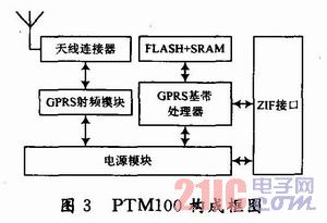
2.1.5 ARM7 processor module The high-performance ARM7 microprocessor LPC2132 provided by Phlips for embedded applications is used as the master controller. It uses ARM's 16/32-bit RISC architecture, the core is ARM7TDMI-S, ultra-small LQFP64 package, 128-bit wide interface / accelerator, operating at up to 60 MHz. It has 64 KB of high-speed FLASH memory and 16 KB of SRAM, and has abundant peripheral resources: 2 32-bit timers (with 4 channels of capture, 4 channels of comparison); 1 10-bit 8-channel A/D converter Converter, conversion time is less than 2.44μs; one 10-bit DAC; PWM channel (6 outputs); 47 GPIOs; 9 edge or level-triggered external interrupt pins; RTC with independent power supply and clock; Serial interface, including 2 industry standard UARTs, 2 high speed I2C interfaces, SPI and SSP with buffering and variable data length. It includes a vectored interrupt controller that can be configured with interrupt priority and vector address. The on-chip boot loader can be implemented in system/online application programming (ISP/IAP) with two low-power modes, idle and power-down. Wake up by an external interrupt.
2.2 Dual electronic lock module The dual electronic lock module consists of six modules: keyboard display module, voice amplification module, password storage module, clock module, RFID code sensing module and SPCE061A processor module.
2.2.1 Voice Amplification Module The voice playback function of Sunplus MCU is very powerful, so the system uses its voice features and adds a lot of information to prompt voice. Simply call the function library to implement audio programming or self-recording voice resources for unique voice playback and voice recognition.
Sunplus MCU SPCE061A comes with dual channel DAC audio output, DAC output is current output, after the audio amplifier is amplified, it can drive the speaker to play.
2.2.2 RFID code sensor module The traditional mechanical lock can be easily opened with the master key. This is the biggest flaw of the modern anti-theft system. In order to solve this problem, the system uses advanced RFID technology. The RFID cipher key is embedded with a 64-bit global unique code ID chip, and there are 700 million combinations that can hardly be cracked, so the thief has no chance. The RFID decoder chip of this design adopts the TE-MIC series U2270B base station chip commonly used in the market. The peripheral circuit of the chip is simple, and has various power supply modes, and the user design is convenient and fast. When an IC card is close to the induction coil, the system starts to detect the RFID number of the card. After the detection is correct, the base station chip U2270B outputs a low level to the single chip microcomputer, otherwise it is a high level. The U2270B can be controlled to operate in a low power state when it is not working normally.
2.2.3 SPCE061A processor module SPCE061A is another 16-bit microprocessor after the SPCE500A series of μ'nSP (Microcontroller and Signal Processor) series introduced by Sunplus. 32 KB of flash memory (FLASH) is embedded in SPCE061A. Compared with SPCE500A, SPCE061A microcontroller with μ'nSP as the core is suitable for digital voice, digital speech recognition and other fields.
The dual electronic lock module of the system uses the chip as a main controller, and realizes a multifunctional, safe and reliable electronic lock by utilizing the high speed, voice and multi-interrupt source of the chip.
3 system software design The system software part includes the main control circuit module program flow chart and the electronic lock module program flow chart.
3.1 Main control module program part The main control module program part includes the main control module main program and the main control module interrupt subroutine, as shown in Figure 4 and Figure 5, respectively. 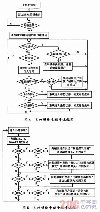
3.1.1 Main control module Main program In the main program of the main control module, the system has been detecting whether there is any incoming call or new SMS message. When there is an incoming call, the system will automatically hang up the phone and then judge whether it is a super user: Yes, start The camera takes a picture and sends it to the super user; no, the system will ignore it and continue to detect. When it is a short message, it is judged whether it is a super user: No, it is judged whether the content of the short message is "888888" or not, the system binds the number to the super user, and replies "the super user is successfully bound"; It is "bf" or "cf", which means that the "bf" system enters the armed state and replies with "successful arming". The "cf" system is disarmed and the "disarming success" is replied.
3.1.2 Master module interrupt subroutine The main module interrupt subroutine is used for alarm processing. When any sensor is triggered, the system will enter the block, start the camera to take a picture, and then take the picture and trigger The location is sent to the bound superuser.
3.2 Electronic lock module program The electronic lock module program flow chart is shown in Figure 6. 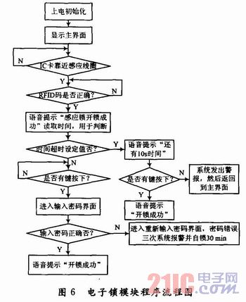
After the program is initialized, enter the welcome main interface and wait for the IC card to be close to the induction coil. When it is detected that the IC card is close, the system starts to verify the RFID code. When the RFID code is correct, the system issues a voice prompt “Induction lock unlocking success†and starts timing. When the time exceeds the set value and has not been within the 10 s delay time. When the lock is unlocked, the system will sound an alarm. After the lock is successfully set within the set time or 10 s delay time, the system enters the main menu interface. The main menu interface has two sub-options: change password and time adjustment. You can change the password and adjust the time.
4 Conclusion In order to make up for the shortcomings of the existing home security system, this paper designs a security system that integrates data acquisition, alarm and remote monitoring. When the surveillance site has illegal intrusion, an alarm is issued. The camera takes a picture of the scene and sends it back to the main control chip. The system sends the captured pictures to the user's mobile phone through the GPRS network to realize the functions of information verification and remote real-time monitoring. In addition, in order to make the system more secure, a dual electronic code lock has been added, which eliminates the thief's use of a master key or other unlocking tools. The whole design is not only simple and convenient to install, but also has high safety and strong information verification, and the system has excellent performance, low cost and great development potential.
12-14 digits Desktop calculator, and many counter modes
