Today, electronic power steering (EPS) has become one of the key elements in reducing carbon dioxide emissions. Therefore, various types of cars are equipped with organic electric power steering systems. So what technologies do you need to implement an electronic power steering system? The EPS is an electromechanical power steering system that replaces the original hydraulic power steering device with an electronically controlled motor. The EPS system takes up less space in the engine compartment, is easier to assemble, and saves fuel consumption. In addition, it no longer uses toxic hydraulic oil in the steering system. In small vehicles, the motor is connected to the steering column through a gearbox, while in a medium-sized car, the motor is mounted on the carrier in an oblique or longitudinal direction using a flange and operates through the gearbox. When the driver turns the steering wheel, the motor powers the steering system. How does the EPS system work? The electronic power steering system consists of a control unit, numerous sensors and a Brushless Motor. The control unit controls the system and provides the information needed by the motor. In addition, it receives information from sensors that are used to measure parameters such as direction angle, driving speed and torque. A sensor that detects motor position and motor current ensures that the motor is operating at its optimum. Figure 1 shows the key components of a high-end electromechanical power steering system with system monitoring. The XC2300 acts as the main processor to control the servo motor and other components. The second smaller microcontroller or ASIC acts as a monitoring unit. Main components in the EPS system The transmission is a three-phase synchronous or asynchronous brushless motor. The rotating field of the motor is generated electronically. A pulse width modulation (PWM) signal with a signal frequency of approximately 20 kHz will affect the speed and torque of the motor. A rotary encoder or magnetic sensor, the so-called giant magnetoresistance (GMS), provides data identifying the rotor position. Usually two phase currents are measured by a shunt circuit or a Hall sensor. The above sensors are all analog outputs and therefore need to be amplified for further processing. The force acting on the steering column and the auxiliary power required by the motor are measured by the torque sensor. Signal processing is done in the control unit. The wheel sensor provides vehicle speed information and the steering angle sensor provides current position information for the steering wheel. Other control units process these signals. The data is transmitted on the CAN bus. Some evaluation logic can be integrated into the sensor, depending on the type of sensor selected for the system. This improves precision and reduces the possibility of errors. The control unit consists of numerous voltage regulators, CAN transceivers, signal processing circuits, bridge drivers, power switches and microcontrollers. The regulator provides the various voltages required by sensors, microcontrollers, and ASICs. The CAN transceiver is used for bridging between the CAN bus and the microcontroller. Whether the data signal processing is analog or digital depends on the type of sensor. Because the microcontroller cannot directly control the power switch (B6 bridge), a bridge driver is required. The bridge driver produces the gate voltage and associated current required to quickly switch the transistor. The intelligent drive also includes a diagnostic interface that detects various problems such as half-bridge shorts, low phase voltages or high component temperatures. The microcontroller controls and monitors the motor and the entire system. It must also perform diagnostic functions and communicate with the network. In addition, another controller is used for error detection and emergency mode is activated when necessary. Since the EPS system is dynamic in the motor and? There are high requirements for torque setting, so they require complex algorithms such as FOC (field-oriented control). This control acts directly on the rotor field of the motor and requires considerable processing power because it involves the operation of multiple coordinate transformations (Clark/Park conversion) and the two phase currents must be adjusted at 50 μs intervals. The motor needs to be controlled by a PWM signal and using a space vector method. Due to the very high performance of the MAC unit, the required CPU load is less than 10%. Figure 1: Key components in an electromechanical power steering system with system monitoring. XC2300 microcontroller The XC2300 microcontroller is a new addition to Infineon's XC2000 microcontroller family, which addresses system monitoring issues, quickly handles rigorous control algorithms, and has extensive built-in hardware support. In short, it handles complex tasks quickly and efficiently. To enhance reliability, the XC2300 uses a Cyclic Redundancy Check (CRC) to verify sensed data in security, involving two writes and a comparison of the two. The entire memory system is protected by a hardware error correction unit. In order to integrate different software modules, a memory protection unit has also been set up. The XC2000 architecture is based on the previously developed C166 core and provides advanced control and DSP functionality. However, unlike the C166 architecture, it has a high-performance pipeline structure that allows instructions to be executed in a single frequency cycle. At the same frequency speed, the XC2300 has approximately twice the processing power of the C166. The XC2300 also incorporates a multiply-accumulate unit that makes it easy to implement matrix operations or finite impulse response (FIR) filter functions. This means that a 16x16-bit multiplication that accumulates 32-bit addition or subtraction can be performed in a single frequency cycle. Fast matrix processing (Clark/Park conversion) and PI controllers play an important role in EPS. The XC2300 supports up to 128 interrupt sources with a total of 16 interrupt levels. In addition to typical interrupt handling, the processor provides an optional DMA transfer function in the form of a Peripheral Event Controller (PEC) that allows large data blocks to be easily moved or copied in a 16MB address space. Program memory access is 64-bit wide and currently supports up to 576KB of embedded flash. The flash memory is physically divided into modules and uses error correction and monitoring functions for higher execution reliability. Each flash area can be read and written protected by a password. The embedded SRAM that can be used to manage data is 50KB. An additional protection mechanism is also employed to prevent unauthorized access to critical CPU buffers. To further improve execution reliability, the protection mechanism can also be triggered when certain restricted instructions are executed or if the CPU stack write overflows. Microstepping is a method of controlling stepper motors, typically used to achieve higher resolution or smoother motion at low speeds. Micro Stepper Motor Micro stepper motor,Micro linear stepper motor,Micro stepping stepper motor Shenzhen Maintex Intelligent Control Co., Ltd. , https://www.maintexmotor.com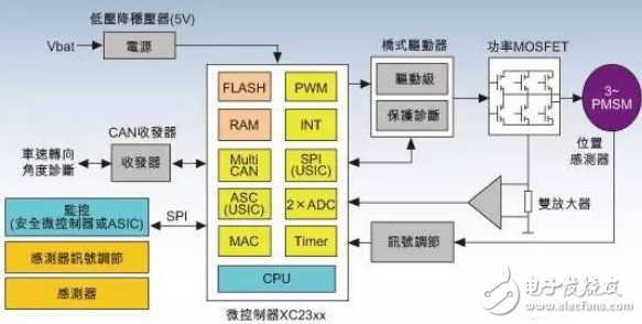
Micro Stepper Motor divides each full step into smaller steps to help smooth out the motor`s rotation, especially at slow speeds.
Microstepping is achieved by using pulse-width modulated (PWM) voltage to control current to the motor windings. The driver sends two voltage sine waves, 90 degrees out of phase, to the motor windings. While current increases in one winding, it decreases in the other winding. This gradual transfer of current results in smoother motion and more consistent torque production than full- or half-step control.