Application area: commercial vehicle CAN bus communication
This article refers to the address: http://
Challenge: The CAN2.0B specification for industrial bus communication, message identifiers and data frame definitions does not form a uniform standard, and parameter definitions are highly arbitrary. The commercial vehicle CAN bus communication standard follows the SAE J1939 protocol based on CAN2.0B. The message identifier ID is a physical definition of parameters such as vehicle speed, engine speed, torque, temperature, pressure, fuel consumption, etc. according to the SAE standard, and the message data frame format corresponds to the encapsulation of the corresponding data content of the protocol data unit. The challenge is to integrate the J1939 protocol into the design of the CAN bus communication platform.
Application: Using the NI LabVIEW software development platform and the CAN communication module in the PXI modular instrument system, create a design method for filtering and identifying the J1939 protocol message identifier ID and multi-frame messages according to the protocol format for receiving and encapsulating transmissions. This method constructs a CAN communication platform; completes the semi-physical simulation of the vehicle's electrical environment, and the CAN bus information transmission, storage, and real-time calculation display of the engine bench test.
Products used:
LabVIEW2009 Software Platform
PXI-1045 chassis
PXI-8108 Embedded Controller
PXI-8464/2 CAN Communication Module
Overview:
Since the beginning of the 21st century, the application of commercial vehicle CAN bus network has developed rapidly. Commercial vehicles that meet the national 3 to 5 emission standards on the market today use the CAN bus network without exception, and carry out the vehicle VECU, engine EECU, automatic transmission ECU, automobile combination meter ECU, and wheel anti-lock brake ECU. Data communication between. Based on the J1939 protocol commercial vehicle CAN bus, the CAN communication interface of the MCU + CAN controller + CAN transceiver for the MCU node of the microcontroller microcontroller has been widely used in the vehicle network control system; The PC or laptop + CAN communication module of the upper computer node of the bench test and the semi-physical simulation test of the whole vehicle electrical environment mostly use the expensive Vector CANoe module.
Problems:
1) The PXI measurement and control device has no CAN communication function based on the J1939 protocol, and cannot meet the functional requirements of the test conditions for CAN bus message information analysis.
2) The CANoe module timing is not controlled by the PXI instrument clock rate and cannot be triggered in synchronization with other measurement parameters of the PXI timing.
Based on the CAN bus communication technology method of LabVIEW and J1939 protocol, the application of PXI measurement and control device in the domestic automotive industry is blank. The difficulty is how to effectively combine the LabVIEW software development platform with the complex J1939 protocol to realize the filtering, receiving and synthesizing of message information. And package delivery.
According to the characteristics of commercial vehicle CAN bus communication network, a CAN bus communication platform based on LabVIEW and J1939 protocol is built. It is embedded in the measurement and control device of NI PXI modular interface for engine bench test and vehicle physical environment semi-physical simulation test.
J1939 protocol
The J1939 protocol is based on the CAN2.0B specification and defines the J1939 encoding system for the CAN2.0B extended frame 29-bit identifier ID, including priority P, reserved bit R, data page DP, protocol data unit PF, and extension unit. PS, source address SA and data byte Data, as shown in Figure 1. These seven parts are encapsulated into one or more CAN data frames through the Protocol Data Unit (PDU) in the Open System Interconnection Reference Model (OSI) application layer, and are sent to other device nodes in the bus network through the physical layer.
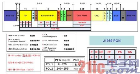
Figure 1 J1939 data frame format
The PDU defines the information related to the J1939 protocol in the data frame, consisting of the identifier ID and the data field.
PDU1 format message PF is between 0 and 239, the message is sent to the destination address from point to point, PS: the destination address received by the message, SA: the source address of the message, and 255 is filled in the destination address as the global address. send.
The PF2 format message PF is between 240 and 255, and the packet is sent to the global address. The PS: parameter group extension value. Most of the J1939 protocol packets are in PDU2 format.
The PDU data field contains the data content in the parameter group. The parameter group number (PGN) is used to uniquely identify the number of the parameter group. One or several parameters constitute one or more frames, and the parameter group is in the application layer. A combination of several parameters (eg, engine water temperature, fuel temperature, etc.) associated with an ECU.
The difference between the J1939 protocol and the CAN2.0B standard
Identifier ID: CAN2.0B Message information for different functions can use the same ID. CAN devices are used according to the manufacturer-specific protocol. When integrated, IDs are not recognized or inconsistent. J1939 The identifier of each frame message is unique, and each frame message has its own PGN, specifying a unique source address for each node, and mapping the source address to the CAN identifier to avoid multiple nodes using the same identifier. Symbol, for example ID: 0CF00400 represents engine speed, torque message.
OSI model: The CAN2.0 specification defines the physical layer and data link layer of the seven-layer OSI reference model. It is the underlying standard. As shown in Figure 2, the compatibility, interchangeability and integration of CAN bus products are poor. J1939 is a high-level protocol for the application layer of the OSI reference model. Signals (parameters) and messages (parameter groups) for vehicle applications are defined at the application layer. The parameters are described by parameters, and each parameter is assigned a number SPN (Suspect Parameter Number), which defines the physical meaning of the bytes in the PDU data field. For example, SPN190 represents the engine speed. There may be several SPNs in a PGN, and the PGN61444 includes parameters such as SPN190 engine speed and SPN513 engine torque.
Multi-frame message: CAN2.0B specification can only use single-frame message transmission. In addition to single-frame message transmission, J1939 protocol also uses conversational and broadcast multi-frame message transmission and performs according to multi-frame data transmission protocol. The packet encapsulation sends and receives a synthetic reassembly process, wherein the conversational multi-frame message transmission and reception node needs a handshake protocol, and the broadcast multi-frame message is sent to the global address.
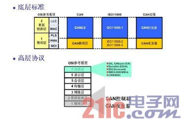
Figure 2 Open System Interconnection Reference Model (OSI)
Module interface
PXI-8464/2 Dual CAN2.0B Communication Interface Module with SJA1000T CAN Controller and TJA1041T High Speed ​​CAN Transceiver and TJA1054AT Low Speed ​​CAN Transceiver. The J1939 data link layer implements packet packing and encapsulation in the PDU format. The CAN controller sends the synchronization, sequence control, error control and flow control that the CAN data frame must have. It automatically generates the CRC check bit and the ACK response bit to insert the data frame. in.
J1939 physical layer protocol specifies up to 30 ECUs per network segment, CAN bus communication rate 250 kBits/s, bus level dominant, recessive, differential voltage 3.5V/1.5V, differential transmission twisted pair cable color CAN -H Yellow, CAN-L green, CAN transceiver completes the matching conversion between the MCU and CAN bus.
software design
The CAN bus message transceiving multitasking process based on the J1939 protocol, as shown in Figure 3, uses a producer/consumer loop data structure. The producer loops through the "element to queue" function to add data to the message cluster queue, and the consumer loops through the "element dequeue" function to remove data from the message cluster queue. The loops use queues to communicate, avoiding multitasking to deal with the competition state. When the production data is faster than the consumption processing data, the buffering effect of the queue ensures that the message data is not lost.
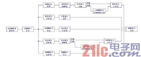
Figure 3 CAN bus communication message transceiving multitasking based on LabVIEW and J1939 protocol
Establish an identification method for receiving packet ID parsing and filtering. The enumerated state variable identification message of the message identifier ID is determined, and the message is filtered according to the condition variable condition structure.
The PDU1 and PDU2 format single-frame messages are all queued. The conversational and broadcast multi-frame messages with the data field greater than 8 bytes are synthesized and reassembled according to the J1939 protocol multi-frame data, and the other message frames without data fields are discarded. After the processed received message cluster is decomposed, the queue is calculated, stored and displayed.
The broadcast frame message is received and synthesized. First, the TP.CM-BAM command frame is parsed, the PGN and the number of frames sent by the EECU are extracted, and the frame number of the received TP.DT-BAM data frame group message is deleted, and the array is replaced by the array. The subset recombines the received message and restores the broadcast frame message whose data length is greater than 8 bytes.
Establish a method for identifying the sent packet ID parsing package. The message parsing first determines the frame type state variable, and secondly, according to the condition of the state variable, the packet format definition is performed.
The PDU1 and PDU2 with the data field less than or equal to 8 bytes send packets directly into the queue. The conversational and broadcast multi-frame messages with the data field greater than 8 bytes are processed according to the J1939 protocol multi-frame data processing. The queue, the processed J1939 sent message cluster is decomposed and out of the queue and written to the CAN port.
Broadcast frame packet transmission and encapsulation. The ID resolution encapsulates the PGN of the transmitted packet in the broadcast packet command frame identifier ID-TP.CM. The packet array is parsed to calculate the number of bytes and the number of frames, and the frame number plus the message is created. The 8-byte multi-frame array of the subset is combined with the data frame identifier ID-TP.DT packet encapsulation cluster to synthesize TP.DT-BAM, and TP.CM-BAM and TP.DT-BAM form a broadcast frame format message.
Application effect
In the semi-physical simulation message receiving test test of the vehicle electrical environment, the CAN bus communication platform based on LabVIEW and J1939 protocol shown in Figure 4 is used to compare and test with the Vector CANoe module at the same time period. The EECU message in the steady state condition is shown in Figure 5. The 526 frame message sent by the EECU is received within one second, and the received message is not lost.
The engine fuel consumption message reflects the fuel economy of the engine in real time. In the commercial vehicle J1939 protocol CAN bus network, it is respectively received by the vehicle VECU, which is used as a shift control strategy to control the automatic transmission car; the combination meter ECU receives and displays in real time, Prompt the driver to form good driving habits and control the car to achieve the best fuel economy road conditions. In order to achieve the best power, economy and emission standards of the engine, the engine electronic control unit EECU needs to be calibrated and matched to obtain the optimal fuel injection pulse width calibration parameters. After the calibration, the comparison test is performed to verify the calibration effect of the EECU.
The engine steady-state test can reflect the constant speed condition of the vehicle; and the engine transient test can simulate the engine state in the actual road cycle. By comparing the fuel consumption of the real-time message with the actual measured transient fuel consumption, the corresponding relationship between the two is studied and the control effect of the engine EECU is judged.
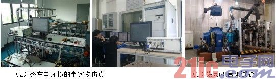
Figure 4 CAN bus communication platform application based on LabVIEW and J1939 protocol
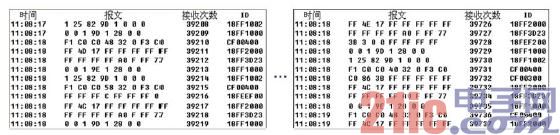
Note: Receive message 39736 – 39210 = 526 in one second
Figure 5 engine steady state EECU message
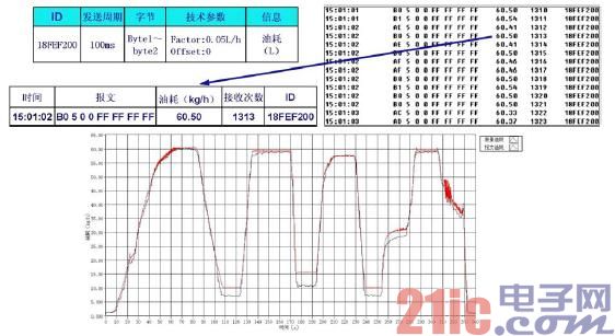
Fig.6 Engine fuel consumption ratio comparison test
The transient fuel consumption ratio measurement curve of a certain engine engine ten working condition test is shown in Figure 6. The EECU fuel consumption message data received and analyzed from the J1939 protocol CAN bus and the measured data of the platform fuel consumption meter exist when the engine is under low load. The difference is that the actual fuel injection amount is small when the engine is under low load, and the difference between the set fuel injection amount and the actual fuel injection amount is large. This difference is due to the large fluctuation of the engine's low-load common rail rail pressure, which causes the fuel injection to fluctuate and the passenger gauge exists. The two curves are generally consistent. The engine injection target value received through the CAN bus is close to the actual measured value, and the change trend and timing are synchronized, reflecting that the engine EECU calibration match achieves the target value of the optimal fuel injection pulse width.
to sum up
Based on the development of CAN bus communication platform of NI PXI modular system architecture based on LabVIEW and J1939 protocol, the application foundation of NICAN module in commercial vehicle CAN bus communication is established. The project has promotion and commodity application prospects. In the engine bench test and the semi-physical simulation analysis of the vehicle electrical environment, the CAN bus message information is filtered, identified, synthesized, received, packaged, stored, analyzed, and displayed in real time.
The LabVIEW software platform's powerful mathematical analysis and queue processing capabilities, as well as NI PXI instruments and CAN interface modules for the harsh test environment of the vehicle, meet the functional requirements of the CAN bus message parsing in the test conditions, and realize the message The data is sampled simultaneously with other measurement parameters of the NI PXI instrument, and the test data is compared and analyzed for real-time and authenticity.
Buffet Server
Buffet Server,Household Restaurant S.S Buffet Server,Heated Buffet Server,Kitchen Buffet Server
Shaoxing Haoda Electrical Appliance Co.,Ltd , https://www.hotplates.nl