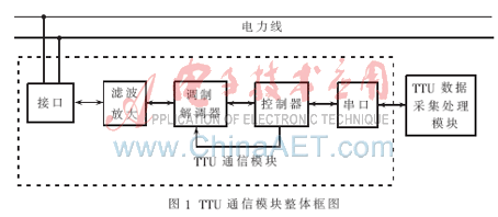
The interface receives the command information from the main station through the power line. After filtering and amplifying, the command is sent to the controller after demodulation, and then the controller sends the command of the main station to the data acquisition and processing module through the serial port. The data collection and processing module collects the data of the distribution transformer according to the received master station command. After analysis and processing, the data information is sent to the controller of the communication module through the serial port, then modulated, and finally sent to the power line through the interface , Waiting for the master station to receive. The microprocessor selects the ARM chip, and it communicates with the TTU data collection and processing module through the serial port, and timely sends the master station's commands and transmits the distribution variable data collected by the TTU. Start word: 2 bytes, 0x0564. When the communication module judges that there is a frame command reception, it starts demodulation, that is, carrier reception, and the limited time is 5 s. During the demodulation process, the frame command is judged at the same time, and if there is, continuous demodulation is resumed. The serial port reception is allowed only when there is a frame command reception, and the limited time is 1.5 s. After receiving the frame command to start demodulation, it sends a command to the serial port. After receiving the command, the TTU data collection terminal performs data collection and processing according to the command's instructions, analyzes the data status, and sends the collection and analysis results to the serial port. When the communication module receives the returned data from the collection end within 1.5 s after finding the frame header, it will modulate the data and send it to the power line, that is, the carrier transmission, with a time limit of 5 s. If the return of the collection end is not received within 1.5 s after the frame header is found For data, it is forbidden to receive data from the TTU collection terminal. After the carrier transmission is completed, the communication module returns to the receiving state again, waiting for the next command from the master station.
In situations which require the use of high powered LEDs and/or a greater number of LEDs in series, a high Power Led Driver is an appropriate addition to the circuit. Care must be used not to overpower the circuit, as this can result in a number of burnt out lights. Applications which commonly require the use of a high power Led Driver include:
High Power Led Driver Constant Current High Power Driver,High-Power Leds Driver,Power Led Driver ShenZhen Fahold Electronic Limited , https://www.fahold.com
1 Hardware design of communication module of distribution transformer monitoring terminal
1.1 Requirements of distribution automation for TTU communication [1]
According to the requirements of the distribution automation system, the distribution transformer monitoring terminal TTU should be able to communicate with the distribution electronic station or the main station, report the real-time information collected by the terminal, and receive various control commands issued by the sub-station / main station at the same time. The following requirements can communicate with the nearby distribution transformer monitoring terminal (TTU) or other intelligent devices. Therefore, the requirements for the communication function of the distribution transformer monitoring terminal are relatively strict.No matter the communication method, communication protocol, and communication interface, they must meet the requirements of the distribution network automation system, mainly including:
(1) Reliability of communication: The communication of the distribution transformer monitoring terminal should be able to resist harsh weather conditions, such as rain, snow, hail and thunderstorms, as well as long-term ultraviolet radiation and strong electromagnetic interference.
(2) Higher cost performance: Consider the cost of the communication system, select the best combination of cost and function and technological advancement, and pursue the best cost performance.
(3) Real-time performance of distribution communication: TTU transmits a large amount of fault data quickly and in time when the power grid is faulty. The communication system of the distribution transformer monitoring terminal must have the capability of two-way communication and half-duplex or full-duplex.
(4) Standardization and versatility of the communication method: The communication system of the distribution transformer monitoring terminal includes a transmitter and a receiver. It is often necessary to communicate with other power distribution equipment in use, so it is necessary to choose a versatile and highly standardized communication method and equipment as easy as possible to use and maintain.
1.2 Composition of TTU communication module
1.2.1 Overall block diagram of the communication module The overall block diagram of the communication module of TTU [3] is shown in Figure 1. 
1.2.2 The choice of power line carrier chip In power line carrier communication, the power line carrier chip plays a vital role, which directly affects the accurate transmission of information, so the choice of power line carrier chip is very important.
XR2210 / XR2206 chip set or LM1893 is an earlier power line carrier chip. XR2210 / XR2206 is a group of FSK modulation and demodulation chips, not specifically designed for power line carrier communication. LM1893 is a modem chip produced by National Semiconductor Corporation. It adopts FSK modulation and demodulation method. It is only a slight improvement to the general FSK modulation and demodulation chip. At present, these two modem chips are basically not used in China. SSC P300 is a power line carrier modem chip designed by Intellon Corporation with the latest modern communication technology. It uses spread spectrum (Chirp mode) modulation and demodulation technology, modern DSP technology, CSMA technology and standard CEBus protocol, which can be called an intelligent modem chip, reflecting the development trend of modem chips. But it is designed by Intellon according to North American frequency standards and grid characteristics, especially for home automation. The frequency range is 100 kHz to 400 kHz, and the grid voltage is 480 Y / 277 Vac, 208 Y / 120 Vac, 60 Hz, which is not suitable for China's 50 Hz grid frequency. ST75xx chip is a modem chip designed by SGS-THOMSON for power line carrier communication. Because it is a dedicated modem chip, in addition to the signal modulation and demodulation function of a general modem chip, it also adds many special signal processing methods for power line applications. At present, it is widely used in the field of power line carrier meter reading in China. This article selects the power line carrier chip ST7538 from SGS-THOMSON, which is a half-duplex, synchronous / asynchronous FSK modem chip designed for power line network communication in the home and industrial fields based on ST7536 and ST7537. ST7538 integrates all functions of sending and receiving data [4]. It can be easily connected to the microprocessor through serial communication. It has automatic voltage control and current control inside, as long as a small number of external devices such as coupling transformers are enough. Connected to the power network, it can achieve reliable communication in a channel environment with a wide noise band. ST7538 also provides watchdog, zero-crossing detection, operational amplifier, clock output, timeout output, +5 V power supply and +5 V power status output, etc., which greatly reduces the number of peripheral devices of the ST7538 application circuit, is a function The powerful and highly integrated power carrier chip is designed for home and industrial environment applications and adopts a variety of anti-interference technologies.
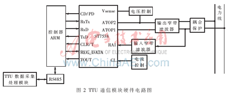
1.2.3 Design of the hardware circuit The communication module includes a microprocessor part, a carrier part, a signal filtering part and a power line signal coupling protection part. The connection of each part of the entire communication module is shown in Figure 2. 
The power line carrier chip ST7538 communicates with the microprocessor through the SPI port, and the data exchange between the microcontroller and the ST7538 can be realized through the serial ports RxD, TxD and CLR / T of the microprocessor and ST7538. The working mode of ST7538 is determined by the status of REG_DATA and RxTx. The communication between the microprocessor and ST7538 adopts synchronous mode, and CLR / T is used as the reference clock. When ST7538 is in the state of receiving data, RxTx is low. The data to be sent enters ST7538 from the TxD pin. It is sampled at the rising edge of the clock and sent to the FSK modulator for modulation. The modulated signal undergoes D / A conversion, filtering and automatic level control (ALC), and then output to the power line through the differential amplifier. When ST7538 is in the state of receiving data, RxTx is high, the signal enters ST7538 from the analog input RAI pin, passes a band-pass filter with a bandwidth of ± 10 kHz, and is fed into an amplifier with automatic gain AGC. This signal is demodulated, filtered and phase-locked into a serial digital signal, which is output to the microprocessor ARM.
The signal filtering part includes two parts: an input narrowband filter and an output narrowband filter. The input filter circuit uses a parallel current resonance circuit to filter out unwanted signals and noise other than the specified frequency. The output filter circuit uses a series voltage resonance circuit to prevent unwanted signals from coupling to the power line.
The power line signal coupling protection circuit is composed of three basic parts: a power amplifier, an output protection matching circuit, and an input gain balance matching circuit. The coupling mode uses capacitive coupling.
2 Software design of communication module of distribution transformer monitoring terminal
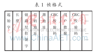
2.1 Formulation of communication protocol The communication protocol of the communication module is formulated according to the DNP3.0 protocol. The data at the data link layer uses a variable frame length format: FT3. An FT3 frame is defined as a fixed-length header, followed by optional data blocks, each with a 16-bit CRC check code. The fixed header contains a two-byte start word, a byte length (LENGH), a byte link layer control word (CONTROL), a 16-bit destination address, a 16-bit source address and a The frame format of the 16-bit CRC check code is shown in Table 1. 
Length: 1 byte, is the sum of control word, destination address, source address and user data, 255≥length≥5.
Destination address: 2 bytes, low byte first.
Source address: 2 bytes, low byte first.
User data: the data block that follows the header, every 16 bytes, the last block contains the remaining bytes, which can be 1 ~ 16 bytes. Each data block has a CRC cyclic redundancy code hanging behind.
CRC cyclic redundancy code: 2 bytes. Within a frame, hang after each data block.
Control word and function code: The communication control word contains the transmission direction of the frame, the frame type and the control information of the data stream. The specific settings of the function code are:
For the original sender's frame:
0: Reset the remote link 1: Reset the remote process 3: Send user data, the other party needs to confirm 4: Send user data, the other party does not need to confirm 9: Inquire the link status For the slave to send the frame:
0: positive confirmation 1: negative confirmation 11: answer to link status
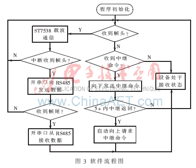
2.2 Software design scheme of the communication module The communication module usually works in the carrier receiving state [5]. After receiving a frame of data, it demodulates to the TTU data collection terminal. The TTU collection terminal receives and returns the data. After the data is modulated, it is transmitted to the master station through the power line. After demodulation to the collection terminal. Carrier transmission is performed when RS485 receives data within a specified time, and returns to the receiving state after the data transmission is completed. If RS485 does not receive data within the specified time, it will automatically return to the carrier receiving state. The software flow of the communication module is shown in Figure 3. 
This paper implements the design of the communication module of the distribution transformer monitoring system. This module is based on the power line carrier communication technology and communicates with the distribution main station through the power line without the need for another line. It has the advantages of good cost performance, high integration and reliable work. The communication module and the data acquisition, analysis and processing module of the distribution transformer are combined to form the monitoring terminal of the distribution transformer. The monitoring terminal of the distribution transformer integrates collection, processing and communication, improving the function of the monitoring terminal of the distribution transformer. The design is optimized, the performance of the entire monitoring terminal is improved, and it has good development prospects.
Fahold offers led drivers over 100W or higher, suitable for high power industrial lights and High way light, both indoor and outdoor can be used, the product quality requirements, safety and stability, high pressure test protection, short circuit protection, anti-lightning strong, safe level Certification, UL TUV FCC, etc. certification.
In the power supply and distribution system, the distribution transformer monitoring terminal (TTU) is used to collect and control the information of the distribution transformer. It monitors the operating conditions of the distribution transformer in real time and can transmit the collected information to the main station or Other intelligent devices provide the data required for the operation control and management of the power distribution system. It is generally required that TTU can monitor the operating conditions of line, column distribution or box-type transformers in real time, find and handle accidents and emergencies in time, and have the functions of local and remote reactive power compensation and on-load voltage regulation. It can be seen that in addition to data collection and control functions, TTU has another important function is the communication function [1].