It is generally believed that for a period of time in the future, the GGE / EDGE network will remain the foundation of global mobile voice and data communications, especially in areas where spectrum resources are scarce. In such a situation, the GGE / EDGE network is very popular because of its low tariff level and numerous service types (while supporting global roaming). Therefore, telecom operators are actively researching, hoping to further improve the performance of existing GGE / EDGE networks. Timeslots (Downlink): time slots (downlink) Figure 2 RTTI USF mode Quick Ack / Nack report Figure 3 Quick Ack / Nack report operation example Downlink Dual Carrier The most significant benefit of Downlink Dual Carrier (DLDC) is that it overcomes one of the major shortcomings of the GSM wireless interface-the 200kHz carrier bandwidth. The peak data rate of DLDC is close to 1Mb / s. Figure 4 Downlink dual carrier operation example Mobile station receive diversity The receive diversity capability can improve the sensitivity and stability of mobile stations in areas of high interference and dense deployment. It improves the receiving performance of the mobile station by using additional antennas. In fact, the introduction of the Single Antenna Interference Cancellation (SAIC) function has met the downlink advanced receiver performance (DARP) requirements, proving that mobile station receiver performance has been enhanced to significantly improve spectrum efficiency. Mobile station receive diversity can further improve the interference cancellation performance of Gaussian minimum frequency shift keying (GMSK) modulated signals. In addition, compared with SAIC, mobile station diversity reception can significantly enhance the interference cancellation performance of 8PSK modulated signals. The meaning of design and test tools Although these new E-EDGE features have many important advantages, they also bring new challenges to design and test work. Design and test tools must be able to configure and test RTTI, FANR, DLDC, and HOM Features. More specifically, they must: Figure 5 The EDGE evolution solution in the Agilent 8960 wireless communication tester can test the new features of E-EDGE in conclusion DIY Drone landing Gear, Carbon Fiber Landing Gear For Drone, Multi Rotor Landing Gear,Electric Retractable Landing Gear DIY Drone landing Gear, Carbon Fiber Landing Gear For Drone, Multi Rotor Landing Gear shenzhen GC Electronics Co.,Ltd. , https://www.jmrdrone.com
EDGE Evolution (E-EDGE) will further strengthen the communication capabilities of GSM / EDGE networks. The 7th edition of the GSM specification stipulates the standards for EDGE evolution. EDGE evolution adds a variety of new features, which can further expand system capacity, support the network to handle increasing data services, while increasing the average data rate and the highest data rate, reducing latency-all of these features can provide users with more Excellent application experience.
Generally, E-EDGE includes 4 optional features:
* Reducing delay through two special methods: fast Ack / Nack report (FANR) and reducing transmission time interval (RTTI);
* Downlink dual carrier;
* High-order modulation (HOM) and high symbol rate (HSR);
* Mobile station receiving diversity.
These characteristics will not affect traditional mobile phones, and no additional frequency resources are required. In addition, except for HSR, these features have no impact on the core network or base station (BTS) hardware. However, they pose new challenges for mobile phone terminal developers and design and test tool suppliers. In order to help users better understand these challenges and understand how to solve these problems, we will introduce the functions of E-EDGE and its test solutions in detail below.
Reduce transmission time interval
E-EDGE can reduce the transmission time interval (TTI) in an enhanced GPRS (EGPRS) connection by pairing two packet data traffic channels (PDTCH) physical channels on different time slots for data transmission. Usually the paired time slots have common frequency characteristics. In this RTTI configuration, PDTCH data blocks that are interleaved on 4 bursts are transmitted on two packet data traffic channels in the form of PDTCH pairs in two frames (as shown in Figure 1). Since the number of frames to be transmitted is halved, the time of the TTI itself is also halved, which is reduced to 10ms. 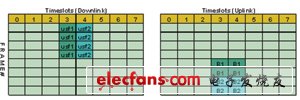
Timeslots (Uplink): time slots (uplink)
FRAME #: data frame number Figure 1 BTTI USF mode
The RTTI configuration can be implemented in any of two uplink status flag (USF) modes: basic TTI (BTTI) USF mode or RTTI USF mode. Figure 1 is a BTTI USF mode for RTTI channel configuration. In this configuration, a given USF is interleaved on the 4 bursts associated with the packet data channel (PDCH). The USF on the lowest PDCH in the PDCH pair allocates resources to the first radio data block period of the next basic radio data block period. The USF on the highest PDCH in the PDCH pair allocates resources to the second radio data block period of the next basic radio data block period. In this way, a different USF can be assigned to the mobile station in each basic radio data block period.
Figure 2 shows the RTTI USF mode for RTTI channel configuration. In this configuration, a separate USF is associated (and interleaved) on each wireless data block on the downlink (DL). The USF allocated in the first radio block period on the downlink can allocate resources for the second radio block period on the uplink (UL) in the same basic radio block period. The USF allocated in the second radio block period on the downlink can allocate resources for the first radio block period on the uplink (UL) in the next radio block period. In this configuration, each PDCH pair can have a different USF. 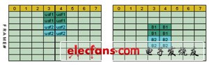
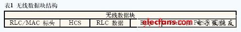
The 3GPP Release 7 Technical Specification specifies FANR in the procedure for reducing latency. Assuming that a wireless data block is used for data transmission in a certain direction, FANR may piggybacked Ack / Nack information, which is related to data transmission in the other direction (for example, related to temporary data block flow or TBF) . This information can be achieved by inserting a fixed-size piggybacked ACK / NACK (PAN) field in the radio link control (RLC) data block. Therefore, after the FANR function is added, the wireless data block used for data transmission is composed of an RLC / Media Access Control (MAC) header, one or two RLC data blocks, and an optional PAN field. Table 1 shows the structure of the wireless data block.
To better understand the concept of FANR, see the example in Figure 3: DL TBF is allocated on time slots 0, 1, 2 and 3 (TBF1) and multiplexed with other TBFs (TBF2 and TBF3). The figure assumes that the RLC data short bitmap (Short bitmap) length is only two 8-bit bytes. 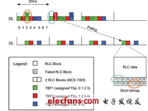
DLDC means that the same terminal can receive or send two carriers on independent carrier frequencies (or MAIO: s in the case of frequency hopping). Figure 4 shows an example. On the left side of the figure is the wireless data block in the 4-slot single carrier allocation, while on the right side is the wireless data block in the 2 × 4 slot dual-carrier allocation. These two frequencies (MAIO: s in the case of frequency hopping) are usually not adjacent. 
High-order modulation and high symbol rate
In the 7th edition of 3GPP, two terms were introduced: EGPRS2A and EGPRS2B, which represent HOM and HSR, respectively. Since EGPRS2B may need to upgrade BTS hardware during implementation, it is generally not as widely used as EGPRS2A in the initial application stage. The following describes the EGPRS2A and EGPRS2B UL and DL.
â— EGPRS2A downlink
EGPRS2A DL provides 8 new modulation coding schemes (DAS-5 to DAS-12), all of which use Turbo coding, as shown in Table 2. 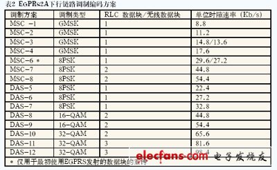
â— EGPRS2A uplink
EGPRS2A UL provides five new modulation and coding schemes (UAS-7 to UAS-11), all of which use Turbo coding, as shown in Table 3. 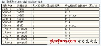
◠EGPRS2B downlink The EGPRS2B DL ​​provides 8 new modulation and coding schemes (DBS-5 to DBS-12), as shown in Table 4. All these schemes use Turbo coding and 325ksymbol / s HSR clock. 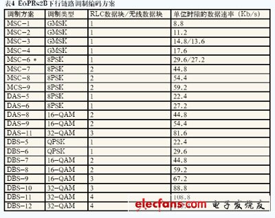
â— EGPRS2B uplink
EGPRS2B UL provides 8 new modulation and coding schemes (UBS-5 to UBS-12), as shown in Table 5. All these schemes use Turbo coding and 325ksymbol / s HSR clock. 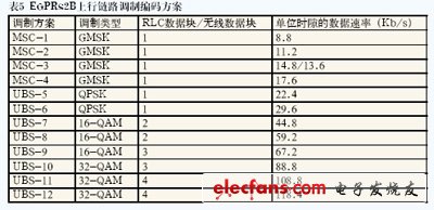
* Provide developers with the ability to select the following modes: TTI mode (BTTI or RTTI) and USF mode (when RTTI mode is selected);
* Provide FANR settings (for example, enable / disable FANR status, event-based FANR status, PAN encoding type, PAN content generation, time-based FANR time conversion, and CES / P fields), allowing flexible setting of FANR test;
* Allow customers to enable / disable DLDC status, configure communication channels, frequency hopping status, MAIO, power reduction, modulation and coding schemes, and support multi-slot configuration of dual carriers;
* Support EGPRS2A UL and DL modulation and coding scheme. 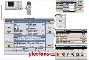
E-EDGE presents new challenges for suppliers of design and test tools. Fortunately, the emergence of new EDGE evolution measurement functions (including protocol-side design verification and RF measurement) provided by the 8960 can solve these problems. Complete and flexible measurement functions will greatly accelerate the development and promotion of E-EDGE.