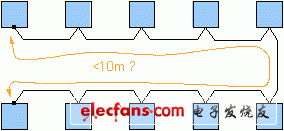
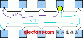
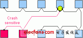
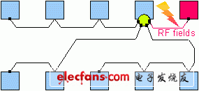
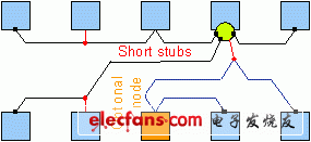
FlexRay has begun to show its strength in automotive electronics applications with single-channel high-speed power transmission, driver assistance and increased comfort. In the new BMW X5 car, FlexRay is used in suspension control, so that engineers and developers can be allowed to use this deterministic protocol with fault-tolerant functions in the safe driving function using dual communication channels and bus monitoring. There is a learning process that gradually adapts to reduce the associated risks. In the development of FlexRay applications, design engineers can build a robust network topology through five basic steps. Step 1: You must first define the number of nodes on the vehicle chassis and their assumed positions before you can determine the Cable length required to implement a passive bus without a stub (a topology called "daisy chain"). The terminal is the cable terminal, as shown in Figure 1. If the cable length is less than 10 meters, the topology is completed, which is considered to be used in series production. Step 2: Once you find that the cable length is greater than 10 meters, you should consider using the "active star" topology (see Figure 2). If the cable length exceeds 20 meters, an active star must be introduced. The simplest active star has only two branches, put the harness? ? Two electrical decoupling components. Because the active star can be enhanced by NXP's TJA1080 transceiver (the first of its kind for BMW X5), the total number of transceivers required has only increased by one. Step 3: If the application can continue to work after the vehicle has a collision accident, the collision sensitive nodes of the system should be distributed on different branches (see Figure 3). In this way, once the cable is squeezed or clamped to a differential voltage, only the data transmission of the affected branch is interrupted, but the active star will ensure that the communication of other branches in the network is not affected. figure 1 figure 2 image 3 Step 4: Given the presence of resonance, nodes or wiring exposed to very harsh RF fields should also be distributed to different branches (see Figure 4). Use one at each end of the cable? ? The terminal (FlexRay electrical physical layer specification v2.1 revision B) transfers the RF induced current to ground. This makes the amplitude of the common-mode voltage on the cable lower without affecting the nodes connected to other branches. Therefore, the jitter in the received data stream can be controlled within a reasonable range. Figure 4 Step 5: To ensure that there are always appropriate (?) Terminals at both ends of the cable (see Figure 5), the end node of the trunk cable should not be an optional node. The electrical position of the node along the cable shall not cause the cable to exceed 10 meters in length. On non-selectable nodes, a short stub (1 meter) can be introduced. Even with greater flexibility, the active star does not have to be at the cable terminal. Figure 5 Verification and optimization Following these five steps helps build a robust FlexRay topology result in terms of electronic characteristics. It is recommended to perform simulation to further verify and optimize the defined topology. Monte-Carlo (Monte-Carlo) simulation method is used to estimate various manufacturing tolerances such as wiring harness, output range and temperature dependent on transceiver and active star. In addition, the FlexRay Alliance has launched a sophisticated cable model that includes the skin effect of the harness. While supporting auto manufacturers to introduce FlexRay, NXP is also continuously improving its professional capabilities in the field of FlexRay topology simulation. About FlexRay applications? ? For more information on terminals, cables, and connectors, see FlexRay Electrical Physical Layer Specification v2.1 Revision B. The electrical physical layer application note v2.1 revision B gives some suggestions on topology design. Both specifications are available through the FlexRay Alliance website. As for the technical details of the TJA1080 FlexRay transceiver, check the NXP website. As long as these recommendations are followed, it can help reduce the power consumption of FPGAs for system design.
Acer has a
reputation as an economy range laptop brand which is designed with price
competiveness in mind. so as a result, the demand for the Acer Laptop Charger is huge.
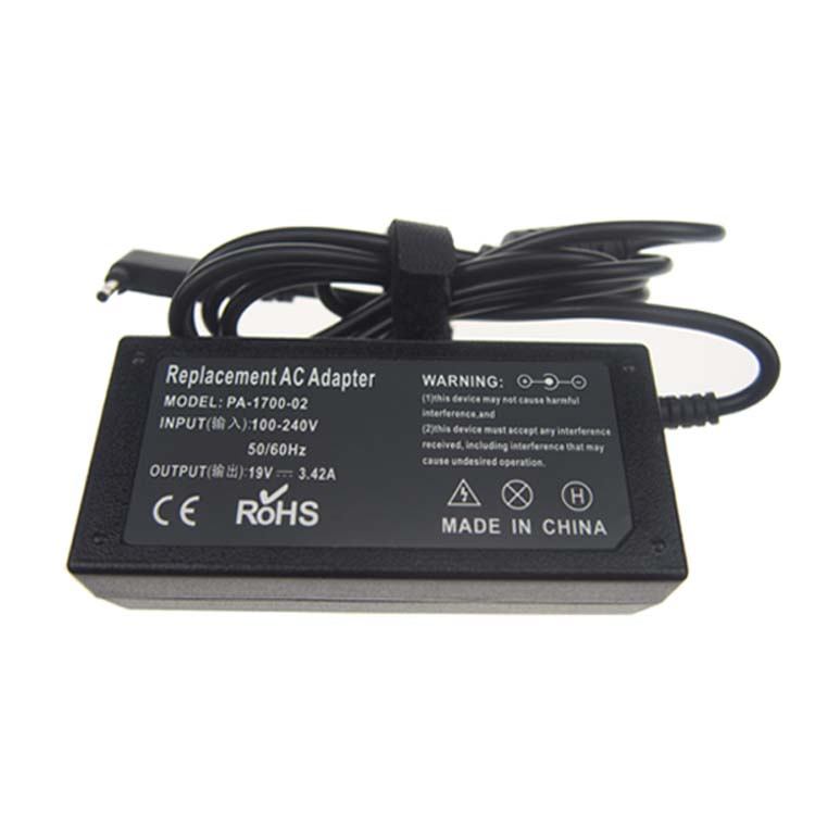
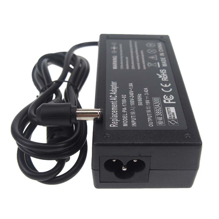
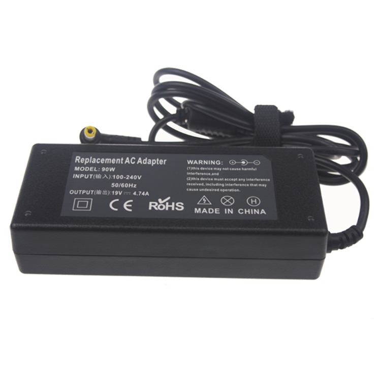
Acer Laptop Charger includes Acer Aspire charger series, Acer TravelMate charger series, Acer Chromebook charger series and so on. The common Acer laptop charger specification
has 19V 3.16A 60W, 19V 3.42A 65W, 19V 4.74A 90W and 19V 7.9A 150W etc, and the
dc tip has common 5.5*2.1mm, 5.5*2.5mm, 5.5*1.7mm and round 4 pin etc.
If your original Acer charger is not work anymore, please
tell us your laptop model, we will help select the correct OEM replacement Acer Adapter for you. Our laptop adapter is with smart IC to protect your
laptop with over current protection, over load protection, short circuit
protection and over heat protection.
Acer Laptop Charger,Acer Computer Charger,Acer Notebook Charger,Acer Aspire Charger Shenzhen Yidashun Technology Co., Ltd. , https://www.ydsadapter.com