Characteristics and applications of wireless power supply integrated circuits
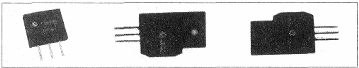
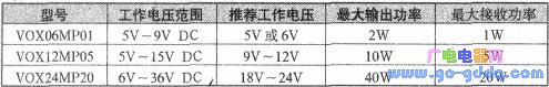
Wireless Power is an old and new topic. Since the invention of Faraday's first generator in 1831, wired power has become a reality. In the long process of two centuries, countless scientists and visionaries hope that one day they will be able to achieve wireless power supply and fight for it. interest. Recently, on the Internet, wireless power-supply applications frequently appear, such as wireless-powered Bluetooth headsets, wireless-powered electric toothbrushes, wireless-powered Christmas trees, etc., especially the wireless power supply of the Massachusetts Institute of Technology, which can be 2m away. It’s amazing to light a 60W bulb! Searching for "wireless power" in google, you can find that wireless power supply is not only practical but also industrialized. The VOXxxMPxx series (x is digital) wireless power supply IC is an example. It has several models, such as VOX06MP01, VOX12MP05, VOX24MP20, etc. After downloading their instruction manuals from the Internet, these models of wireless power supply lC have different working voltages and wireless power supply capabilities, which are 1W, 5w and 20W respectively. Refers to the actual received power of the receiving end), its application circuit is very simple, there are very few external components, only two or three common capacitors or resistors, the price is relatively cheap. The shape below is as shown below.
First, the main features of VOXxxMPxx:
1. Three- or four-pole structure, thick film package.
2. DC-AC conversion, simple application circuit and convenient debugging.
3. The transmitting coil and the receiving coil are completely separated. The transmitting coil is outside the appliance, the receiving coil is in the appliance, and the electric energy is transmitted from the outside of the appliance to the inside of the appliance. Therefore, the wireless transmission of the power (wireless connection) is realized, and the complete separation of the power source and the appliance is realized, and the power is enhanced. Electrical safety, flexibility, water resistance, etc.
4. The number of turns of the transmitting coil and the receiving coil is small, it can be operated in only a few turns, and the shape can be arbitrarily changed, and is suitable for different electrical appliances.
5. Works without relying on any media. The wireless transmission of electricity can pass through a variety of media, such as air, wood materials, glass, water and other non-metallic media, and achieve the same function and efficiency. However, close to the metal will seriously affect its work efficiency.
6. It does not interfere with common household appliances during work, and is harmless to humans and animals, and does not affect magnetic card data.
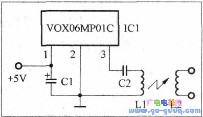
Second, the working circuit
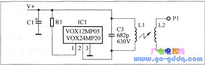
The typical working circuit of VOX06MP01, VOX12MP05, VOX24MP20 is shown in Figure 2 and Figure 3.
The working circuits of VOX12MP05 and VOX24MP20 are the same, the difference is the working voltage and output power. See the table below.
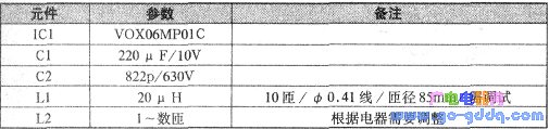
The component parameters in the above figure and the following figure are as shown in the above table and the table below.
Third, the working principle
It can be seen from the above circuit that the receiving portions are completely identical, and each has only one air-core coil L2, which is a receiving antenna, and the transmitting portion has an air-core coil L1, which is a transmitting antenna.
The working principle of this type of IC is electromagnetic induction. Mainly through the magnetic field to transfer electrical energy, that is, a higher frequency power inverter (the principle will not be described again). Different from traditional inverters, they use air-core coils, and the number of turns is very small, only a few turns (usually about 10 )), the two coils can be completely separated, and received at low power (such as lighting LED lights) Under the premise, the maximum distance can reach about 30cm. On the premise of high power reception, the distance is only a few millimeters. More interestingly, various non-metallic media such as air, water, glass, plastic, wood, etc. are allowed between the two coils, which embodies an important characteristic: the power supply of the partition.
The voltage at the receiving end is adjusted by changing the number of turns of L2.
Fourth, the scope of application
Since such wireless power supply ICs have the function of providing power for the partition, the traditional wired power supply mode is broken, which is an extension and supplement of the wired power supply. Therefore, it has a wide range of applications and application prospects, and its application range is summarized into three categories, namely:
1. Power or charging of small mobile appliances such as razor charging, watch charging, and robot charging.
2. Underwater power supply and waterproof appliances, such as underwater lighting, underwater blasting, fish tank lighting, electric blankets, etc.
3. Electrical appliances or places that cannot be realized by wired power, such as various types of sensors or detectors and certain military sites.
Fifth, debugging
1. The relationship between shape and size of L1 and L2
The shape of L1 and L2 should be similar, as if it were a circle, a square, etc., and L2 is not larger than L1.
2. Spatial relationship between L1 and L2
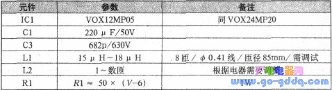
For the VOX06MP01, it is a two-way transmission, and L2 is on both sides of Ll, with the same effect. For VOX12MP05 and VOX24MP20, they are unidirectionally transmitted, and the magnetic field strengths on both sides of L1 are different. Therefore, the receiving efficiency of L2 is different. When L2 is closely adjacent (parallel) to L1, it has the best transmission efficiency, and the efficiency is better than the full embedding. As shown below.
3. Transmit power adjustment, that is, adjustment of input current
The transmission power has a direct relationship with the operating voltage, and the voltage has a high transmission power.
When the voltage is constant, the debugging methods of the above three ICs are similar. A current meter can be connected in the transmitting end to change the number of turns of L1, and the current will change accordingly. Usually, when the current is at its maximum, L1 is fixed.
4. Receive efficiency adjustment
In order to enhance the receiving effect and improve the receiving efficiency, an adjusting capacitor can be connected in parallel at both ends of the receiving coil L2. The size of this capacitor is determined according to the actual effect, usually several thousand picofarads, and the withstand voltage is determined according to needs.
Six, application examples
1. AC power supply
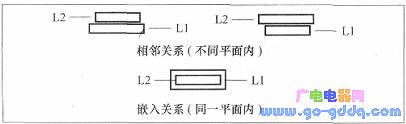
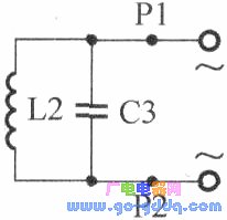
The receiving appliance is shown in the figure below. This method is suitable for powering non-inductive appliances, such as heating wire heating, LED lighting (underwater lighting).
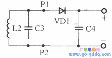
2. DC power supply (charging)
The circuit is shown in the figure below. This method is suitable for powering or charging DC equipment. Such as DC motors, mobile devices, DC audio equipment, DC meters and so on.
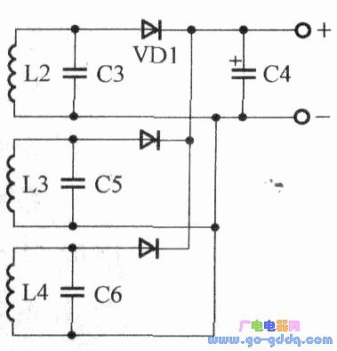
3. Full range of reception
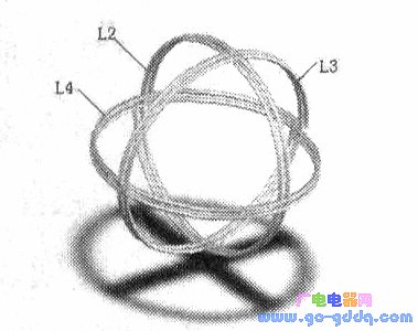
As shown in the figure below, the three coils are placed in three planes perpendicular to each other and connected in parallel to form a sphere. This is an all-round power supply that provides internal power to the appliance. When it is rotated to any orientation, it can be better. The energy from the transmitting coil L1 is received, regardless of whether Ll is in any plane nearby. This method is especially suitable for wireless power supply of spherical or spheroidal moving bodies.
The spatial arrangement of the three coils is shown in the figure below.
Seven, the solution to the EMC problem
Any metal (including aluminum foil paper, etc.) can fully absorb the magnetic field emitted by such ICs. Therefore, a metal film is placed on the outside of the transmitting coil and the receiving coil (2 cm away), so that the excess magnetic field can be fully absorbed. Prevent leaks (although their magnetic fields are harmless to common appliances, humans, and magnetic cards).
FC Optical Fiber Adapter,Sc Optical Fiber Adapter,Short Ear Sc Adapter
ShenZhen JunJin Technology Co.,Ltd , https://www.jjtcl.com