O.D114MM Hydraulic Dc Motors,O.D114MM Hydraulic Dc Motor,O.D114MM Dc Hydraulic Pump,O.D114MM Dc Hydraulic Pump Motor Wuxi Jinle Automobile Motor Factory , https://www.wxjldj.com
This article introduces the implementation of a program for driving an 8-digit digital tube display using two 8-bit AVR microcontrollers. The main program code demonstrates how the ATmega series AVR microcontroller, in combination with the 74HC595 shift register, controls the display.
The following is the core code used in this project:
```c
#include
#include
#include "hc595.h"
// Common anode LED segment code
unsigned char Led_Disbuf[10] = {0xC0, 0xF9, 0xA4, 0xB0, 0x99, 0x92, 0x82, 0xF8, 0x80, 0x90};
unsigned char ComBuf[8] = {0x01, 0x02, 0x04, 0x08, 0x10, 0x20, 0x40, 0x80};
// Function declarations
extern void Delayus(unsigned int lus);
extern void Delayms(unsigned int lms);
int main(void)
{
unsigned char i;
PORTB = 0xFF; // All LEDs off
DDRB = 0xFF; // Set PORTB as output
HC595_port_init();
while(1)
{
for(i = 0; i < 8; i++)
{
PORTB = Led_Disbuf[i]; // Send segment data
HC595_Send_Data(ComBuf[i]); // Select digit
Delayus(70); // Delay
HC595_Send_Data(0x00); // Disable digit
}
}
}
```
Here’s the delay function implemented in the code:
```c
void Delayus(unsigned int lus)
{
while(lus--)
{
_delay_loop_2(4); // 4 clock cycles = 1 μs at 16MHz
}
}
void Delayms(unsigned int lms)
{
while(lms--)
{
Delayus(1000); // 1ms delay
}
}
```
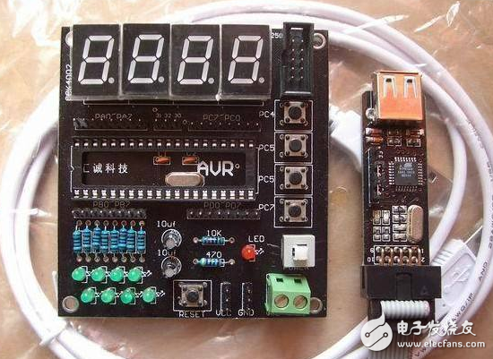
The image below shows the implementation of the 8-digit digital tube display using two AVR microcontrollers.
**Modular Programming – .h File**
Below is the header file for modular programming in this example:
```c
#ifndef __HC595_H__
#define __HC595_H__
#include
#include
// Define pins for 74HC595
#define HC595_latch (1 << PG1) // RCK pin
#define HC595_sclk (1 << PG0) // SRCLK pin
#define HC595_oe (1 << PG4) // OE pin
#define HC595_data (1 << PG2) // DS pin
// Port manipulation macros
#define SET_HC595_latch (PORTG |= (1 << PG1))
#define CLR_HC595_latch (PORTG &= ~(1 << PG1))
#define SET_HC595_sclk (PORTG |= (1 << PG0))
#define CLR_HC595_sclk (PORTG &= ~(1 << PG0))
#define SET_HC595_data (PORTG |= (1 << PG2))
#define CLR_HC595_data (PORTG &= ~(1 << PG2))
#define SET_HC595_oe (PORTG |= (1 << PG4))
#define CLR_HC595_oe (PORTG &= ~(1 << PG4))
// Function prototypes
void HC595_port_init(void);
void HC595_Send_Data(unsigned char byte);
void HC595_Output_Data(unsigned char data);
#endif
```
The corresponding `.c` file contains the actual implementation of the functions:
```c
#include "hc595.h"
// Initialize 74HC595 port
void HC595_port_init(void)
{
PORTG = 0x00;
DDRG |= (1 << PG0) | (1 << PG1) | (1 << PG2) | (1 << PG4);
}
// Send one byte to 74HC595
void HC595_Send_Data(unsigned char byte)
{
unsigned char i;
for(i = 0; i < 8; i++)
{
if(byte & 0x80)
SET_HC595_data;
else
CLR_HC595_data;
byte <<= 1;
SET_HC595_sclk;
CLR_HC595_sclk;
}
SET_HC595_latch;
CLR_HC595_latch;
}
// Send a single data byte
void HC595_Output_Data(unsigned char data)
{
CLR_HC595_latch;
HC595_Send_Data(data);
SET_HC595_latch;
}
```
This setup allows the AVR microcontroller to control an 8-digit display efficiently by using the 74HC595 shift register to expand the number of available output pins. The modular approach makes it easy to reuse and modify the code for different applications.