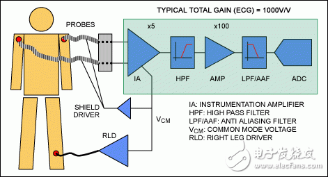
Overview The electrodes are placed on both sides of the heart and attached to the skin, and an electrocardiograph (ECG or EKG) records changes in the ECG signal over time. ECG shows the pressure difference between pairs of electrodes representing myocardial activity. The heart rate signal is indicated on the display to allow the doctor to diagnose weak signals in different parts of the myocardium. The actual ECG signal has a amplitude of only a few millivolts and a frequency of no more than a few hundred hertz. ECG measurement faces many challenges: on the one hand, 50Hz to 60Hz capacitively coupled interference from ECG mains is much stronger than the useful signal; on the other hand, the contact impedance of the body skin and the impedance mismatch between the sensors, which leads to larger The deviation and reduce the common mode rejection; in addition, the contact noise and the interference caused by the electromagnetic source are also solved. In most designs, these signals are extracted using an analog front end (AFE), the signal is amplified and filtered, and then a 12- or 14-bit ADC is used for data acquisition. This article presents the main AFE components of the ECG system and provides a highly integrated design, the MAX11040K 24-bit simultaneous sampling Σ-Δ ADC. The MAX11040K provides the circuitry needed for this application, eliminating the need for an AFE. AFE unit The analog front end contains three main components (Figure 1). Figure 1. A typical ECG device typically uses AFE for signal amplification, filtering, and then data acquisition through an ADC. 1. Instrumentation Amplifier (IA) The main task of the instrumentation amplifier (IA) is to reject common mode signals (usually 50Hz/60Hz interference). ECG applications require a common mode rejection ratio (CMRR) of 90 dB or even higher to suppress 50 Hz/60 Hz signals coupled from the power supply before the amplifier circuit. Even with IAs with high common mode rejection ratio (CMRR), the difference between different ECG electrodes or the mismatch between skin contact impedances not only produces offset drift, but also causes the CMRR to be below the desired level. The impedance mismatch is mainly due to physical contact between the electrodes and the skin, perspiration and muscle movement. The next factor to consider is the gain of the IA. To set the IA gain, care must be taken to avoid clipping or saturation due to excessive gain. It should also be noted that the audio signal is not in the same frequency band as the ECG signal. Therefore, typical audio amplifiers and sigma-delta ADCs are not suitable for ECG applications, which have high input reference noise in the wanted signal band. The input impedance of the IA is also important because the ECG measures weak signals. It is recommended to choose an IA with a high-impedance input because a lower input impedance will result in greater signal attenuation. 2, high pass filter Although the initial signal is only on the order of mV, it will rise to tens of millivolts after being amplified 5 or 10 times by IA. This level of signal can only cover a small part of the ADC input range. For example, a 12-bit ADC has an input range of ±4.096V and a least significant bit (LSB) of 2mV. If you directly acquire tens of millivolts of signal, there is not enough resolution to distinguish between signal and sample noise. Therefore, the signal needs to be amplified again, and the DC drift must also be eliminated. A common AFE circuit uses a high-pass filter that takes unwanted signals (low frequency interference) as a negative offset feedback (negative feedback) to the IA input. 3, the second level of amplification After eliminating dc and low frequency interference with IA and high-pass filters, a second stage of amplification is provided to provide additional gain to reach the input range of the ADC. Some designs have also added a notch filter to further suppress 50Hz/60Hz. 4, low pass / anti-aliasing filter The low-pass filter is used to reject high-frequency interference, and it acts as an anti-aliasing filter (ie, blocks any signal greater than the Nyquist or 1/2 sampling frequency, avoiding ADC aliasing). To further reduce the input common-mode signal, the ECG design typically also introduces a first-level "right-leg driver" that drives the inverted common-mode signal back to the human body. To ensure patient safety, an operational amplifier and a current limiting resistor are typically used to ensure that the drive to the human body is a very weak source. This shielding device is intended to reduce the noise coupling of the signals carried by the ECG probe. In summary, the useful signal in ECG applications is less than 100mV, which is typically amplified to 2V, taking into account offset and common mode signals. Therefore, the AFE must have a 2V measurement range, which can identify signals below a few hundred or even tens of μV, and the sampling rate is around 1ksps. The right ADC can reduce or even eliminate the need for AFE After the AFE design is completed, there are many ADCs that can meet the requirements of resolution, rate, and input range for practical applications. However, ADCs with high resolution, high common-mode rejection ratio (CMRR) and other advantages are still a priority to ensure ECG design requirements. The MAX11040K synchronous sampling, Σ-Δ ADC itself's performance specifications exceed the minimum requirements of such applications, can replace most of the system's functional circuits, and even save the AFE, providing a more reliable, smaller package, and easier Design. The MAX11040K has several essential specifications to apply: SNR >110dB 19-bit noise-free range Effective resolution = 2/219 = 3.8μV Cascading up to 32 channels for simultaneous sampling
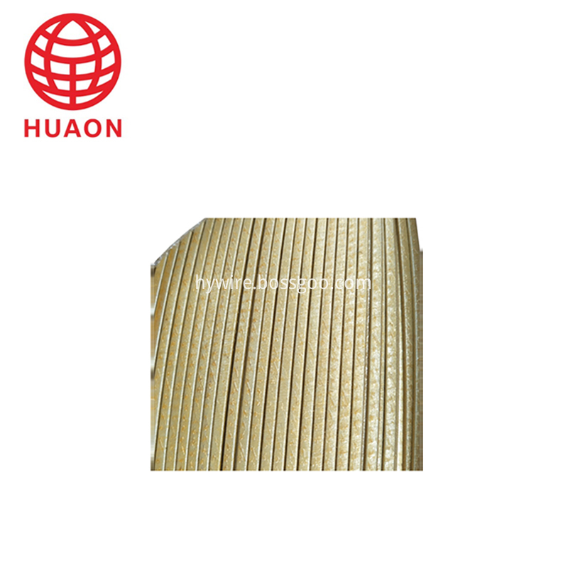
Glass-fiber covered polyester film covered rectangular copper (aluminium) wire .includings Glass-fiber Polyimide Film Covered Flat Copper Wire, Glass-fiber Polyimide Film Covered Flat Aluminium Wire, Glass-fiber Polyester Film Covered flat Copper Wire , Glass-fiber Polyester Film Covered flat Aluminium Wire, Glass-fiber Covered flat Copper wire, Glass-fiber Covered flat Aluminium wire.
Packaging of Products
30/50/150 kg wooden spool
Application: medium and large electrical motor and transformer windings
Film Covered Wire Aluminium Wire,Film Covered Wire,Polyimide Film Covered Copper Wire,Film Covered Flat Wire HENAN HUAYANG ELECTRICAL TECHNOLOGY GROUP CO.,LTD , https://www.huaonwire.com
![]() Input range: ±2.2V
Input range: ±2.2V ![]() Differential input
Differential input ![]() 110dB common mode rejection ratio (typical)
110dB common mode rejection ratio (typical) ![]() 24-bit resolution:
24-bit resolution: ![]() ±6V input overvoltage protection
±6V input overvoltage protection ![]() Quad Fully Differential Synchronous Sampling ADC
Quad Fully Differential Synchronous Sampling ADC ![]() Programmable output data rate
Programmable output data rate ![]() Serial interface (convenient for safe isolation)
Serial interface (convenient for safe isolation) ![]() Programmable phase (sub data rate)
Programmable phase (sub data rate) ![]() Overvoltage/fault detection
Overvoltage/fault detection
About Film Covered Wire
