In addition to a small part of the resistors and capacitors used in simple radios, most of the values ​​are not required to be very accurate. There are many resistors and capacitors that are based on tests, or designed and selected according to what kind of equipment you have. Moreover, the component product itself also has errors, even the error is as large as 20%. However, enthusiasts who are new to radio production do not understand this. When imitating the circuit designed by others, they are not good at using their own components with similar numerical values ​​to substitute, but they purchase additional parts with the same values ​​as those introduced by others. This is not necessary, and the best results may not be obtained. Via In Pad PCB Via In Pad PCB Via In Pad PCB,6Layer Via In Pad PCB,Touch Pad PCB,Via In Pad Storm Circuit Technology Ltd , https://www.stormpcb.com
This article gives some introductions to the functions of various resistors and capacitors commonly used in simple radios, the allowable range of values, and the principles of variety selection for your reference.
The picture is a comprehensive circuit diagram of a DC three-lamp regenerative radio. The so-called synthesis is to draw all common circuits together. But in fact not every radio has so many stages and parts. Enthusiasts can choose according to their own designed or selected lines and this picture.
Selection of capacitors
C1-antenna cross-connect capacitor
Because it is a high-frequency path, a mica dielectric or ceramic dielectric capacitor should be used. A high-quality non-leakage paper dielectric capacitor is also available; and because its value needs to be determined according to the length of the antenna, fine-tuning ceramic dielectric capacitors are commonly used The commonly used value is 25 ~ 1000 pico method (PF). The small value of this capacitor can improve the selectivity of the radio, and the large value can improve the sensitivity. If the antenna is long, use a smaller one. If the antenna is short, use a larger one.
C2-Tuning variable capacitor, or single variable capacitor
Most of our products are 360 ​​picofarads (that is, 0.00036 picofarads); there are also 495 picofarads. The latter covers a wider band, but is much larger; a new product in recent years is 460 picofarads. Pocket radios require small components, and solid media can be used; however, the performance of air media is better.
C3——Detection level grid detection capacitor
It is also a high-frequency channel, and its quality directly affects the performance of the radio. Therefore, high-quality capacitors, such as mica media or ceramic media, are used; paper media are also barely available, but there is no leakage. The general value when receiving a medium wave radio station is 250 picofarads, but if it is selected between 100 and 300 picofarads, the performance of the radio does not change significantly.
C4-Regenerative series capacitor
Its function is to prevent the regenerative variable capacitor from short-circuiting the high voltage by bumping or touching the ground. The common value is 0.01 microfarads (μF). It is sufficient to use paper. The required capacitance is not strict. Larger and smaller can be used, but the minimum is not less than 100 picofarads.
C5-Regenerative variable capacitor, the common value of the product is 100 picofarad
It can be replaced with 360 pico-variable capacitors, but at this time C4 should be used smaller, such as 200-500 pico-farads. This can reduce the effective capacitance after C5 is fully screwed in, making the control easier.
C6-Detector grade screen grid bypass capacitor
Commonly used 0.05 microfarad paper fixed capacitors, the machine can work normally in the range of 0.01 ~ 0.5 microfarad, but it is better to use the larger one in the possible range.
C7——Detection level screen load bypass capacitor
The requirements are not high, the paper is enough, and the capacitance value can be selected within the range of 100-1000 picofarads. This capacitor is only needed when a potentiometer is connected in parallel to the regeneration coil to control regeneration, and there is a low discharge level. The value is large and the regeneration is strong, and the value is small and the regeneration is weak.
C8——Coupling capacitors, or cross-linked capacitors
There are several places in the picture with such capacitors, the selection principle is the same. Commonly used 0.01 microfarad paper capacitors, as long as there is no leakage. The capacity can work normally in the range of 0.006 ~ 0.1 microfarads. The pocket radio can use a smaller value and the volume can be smaller. When its capacity is small, the volume will be slightly lower, especially for the bass weakening, but if you use headphones, there is no problem that the bass is not rich. If the gate-drain resistance of the next stage is used larger, then C8 cannot be used too much.
C9——Voltage amplifier stage bypass capacitor. The selection principle is the same as C6.
C10——Voltage amplifying screen bypass capacitor. The capacitance range is usually 100 to 1000 picofarads; paper media is sufficient.
C11-tone capacitor
It bypasses a part of the high-frequency audio output by the power amplifier stage and does not pass it to the speaker, so that the sound does not sound too harsh and more mellow. Commonly used paper dielectric capacitors of 0.002 microfarads can be selected from 0.001 to 0.006 microfarads, and 0.1 microfarads are also useful. When the volume is large, the bass is richer, but if it is too large, the sound is too dull and unpleasant.
C12——filter capacitor
Commonly used 8 to 30 microfarad electrolytic capacitors. Its function is to prevent self-excitation and howling from occurring when the battery is worn out due to the increase in internal resistance of the battery.
Selection of resistance
When selecting resistors, use more carbon film resistors if conditions permit. Such resistors have good quality, small size, accurate resistance, stable operation, and low noise during operation. But another type of carbon rod resistor (or carbon resistor or synthetic resistor) is cheaper and is often used by enthusiasts. The current of the DC radio is small, so the resistance of the resistor is not large. Except that the power of the R10 should be larger, generally 1/4 to 1/2 watt is enough.
R1——Detection level gate leakage resistance
Commonly used is about 2 megohms, which can vary from 1 to 5 megohms (ΜΩ). A few lines use 10 megohms. The resistance of this resistor is often determined by the power supply voltage used by the radio. The higher the voltage, the smaller the value. This regeneration will be more stable; if the voltage is low, use a larger one, so that the sensitivity will be improved. Generally, it is determined to change one by one according to the listening effect when the installed machine is listening.
R2-adjust the potentiometer for regeneration
It is best to use 10 kilohms (KΩ), the adjustment is more detailed, and 50 kilohms can also be used, but the adjustment is coarser. If you use more than 100 kilohms, you need to use the method of parallel resistance to improve, otherwise it is difficult to adjust.
R3-Detector-level curtain buck resistor
When R4 uses about 250 kilohms, R3 usually uses 1 megohm to 2 megohms; when R4 uses about 50 kilohms or replaces with an inductive coil, it usually uses 20 kilohms to 50 kilohms. The size of this resistor will affect the regeneration strength. If it is used small, the curtain voltage increases, and the tube gain increases, and the regeneration will be stronger. Some circuits use potentiometers instead of this resistor to control regeneration, and its effect is very good. Commonly used potentiometers of 50 kilohms, 100 kilohms or 500 kilohms, the number of which is determined by the required size of the original grid resistance. For safety reasons, it is better to connect a resistor between 30 kohm and 100 kohm in series between B + and this potentiometer.
R4——Detection level screen load resistance
Its resistance is determined by the power supply voltage of B. When B is used at 45 ~ 67.5 volts, the common value is 100 kohm to 300 kohm. When B + is used at 15 ~ 22.5 volts, the common value is 20kohm to 50kohm. Originally used larger, the output sound is louder. But if the B voltage is not high, the regeneration may feel insufficient after being used too much; otherwise, the regeneration will be stronger, but the output audio voltage is smaller. The selection principle is to ensure that it is better to use a larger one when the regeneration is sufficient, which can be decided during the test machine.
R5-Volume control potentiometer
Commonly used are 500 kohms, 470 kohms and 560 kohms, and 1 megohm is also useful.
R6——Gate leakage resistance of voltage amplification stage
Commonly used values ​​are 500 kilohms to 1 megohm. Some machines use large grid leakage bias, R6 will be as large as 5 megohm ~ 10 megohm. If it is small, the output volume will be small. Generally, it is better to use a larger point. However, it is necessary to consider the type of the tube and to consider it with the cross-connect capacitor. When R6 is used very large, C8 should be smaller.
R7——Voltage amplifying grid resistance. Commonly used values ​​are 1 to 2 megohms.
R8——Voltage amplifier load resistance
Commonly used values ​​are 100-300 kilohms. Its value is also determined according to the power supply voltage level of B electricity. However, this stage does not have the problem of regeneration strength, so it is generally used larger than the detection level.
R9——Gate drain resistance of power amplifier stage
Commonly used values ​​are 500 kilohms to 2 megohms. When R9 is used larger, C8 should also be smaller.
R10——Negative voltage resistor of power amplifier stage
Its value will affect the amplification performance and signal fidelity of the power amplifier tube. Because this grid negative pressure is formed by the DC current flowing through each tube of B-. In order to maintain a certain bias, R10 will depend on how many tubes the radio uses. When there are only 1 to 2 tubes, R10 usually uses 700 to 800 euros; when there are 3 to 4 tubes, 400 to 500 euros; when there are 5 to 6 tubes, 200 to 400 euros. This resistor has the function of protecting the tube filament. If it is a low-B radio, there is no need to have this resistance. (Zhou Zhaozao) 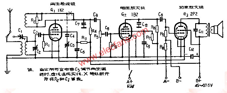
What is Via In Pad? In shortly,via in pad is the via holes are at the SMD pad.The vias are very small,usually under 0.3mm.Why and how? First is there is no enough space to layout,you have to put the vias and holes closer even together.Second it helps thermal management and for high frequency boards,it may help improve signals.
Because the SMD pads are for SMD components loading,so the solder can not flow to inner layer or the other side when assemble.That is the most important for via in pad board.
How PCB manufacturers like us to do via in pad board? We will fill all vias with non-conductive epoxy and plate copper over it ,so the vias are flat same as others. Many PCB factories are unable to do such capability.
The key technology is how we fill vias and guarantee there is no any solder (surface finishing) in the holes.
Filled via in pad is a way to achieve intermediate density with an intermediate cost compared to using blind/buried vias. Some of the key advantages associated with using the via in pad technology are:
.Fan out fine pitch (less than .75mm) BGAs
.Meets closely packed placement requirements
.Better thermal management
.Overcomes high speed design issues and constraints i.e. low inductance
.No via plugging is required at component locations
.Provides a flat, coplanar surface for component attachment
Via in big pads are not a big problem.but for BGA,that is technology.As BGA pads are very small,10mil or 12mil,and there is no enough space.Manufacturing is not easy as other boards.