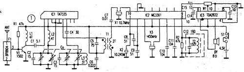
The main difference between auto-searching FM radios and ordinary FM radios is their different tuning methods. The automatic search FM radio adopts the electric tuning method to select the radio station, eliminating the need for a variable capacitor, and setting two touch buttons of "search" and "reset". As long as you press the search button during use, the radio will automatically search for a radio station. When it finds a radio station, it will tune in accurately and stop. If you want to change a radio station, just press the search button again, and the radio will continue to search for radio stations towards the higher end of the frequency. When you tune to the highest frequency, you need to press the reset button to return the radio local oscillation frequency to the lowest end before you can start searching for the station again. This automatic search FM radio is easy to use and accurate to tune. Because it does not use variable capacitors, it has a long service life (variable capacitors are easy to damage). Its disadvantage is that there is no frequency indication. In the radio frequency receiver from the antenna, oscillator, mixer, AFC (frequency automatic control) circuit, IF amplifier (IF frequency is 70kHz), IF limiter, IF filter, discriminator, low frequency squelch circuit, audio All functions such as output are also equipped with search tuning circuit, signal detection circuit and frequency locked loop. Follow WeChat Download Audiophile APP Follow the audiophile class related suggestion The following introduces a highly sensitive FM radio suitable for weak signal areas and remote mountain areas, ... '+ data.data.username +' '; dom + ='
Product Features
1, built-in over-current overheating, temperature control circuit technology.
2, the module design, easy installation, online replacement.
3, low leakage current, fast response time, low residual voltage.
4, alarm indication device, green (normal) v red (fault).
Maximum Discharge
Current Imax(8/μ20μs)kA
Nominal Discharge
Current In(8/μ20μs)kA
Operating
Environment-C
Surge Protector SPD,Surge Protection Device SPD Wenzhou Korlen Electric Appliances Co., Ltd. , https://www.korlenelectric.com
First, the working principle of the circuit Figure 1 is an electrical schematic diagram of automatic search for FM radio. The core device is a TDA7088 integrated circuit, which contains 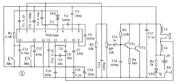
The variable capacitor is replaced by a varactor diode, which is a special kind of diode. Its PN junction capacitance changes as the bias voltage (reverse voltage) on the PN junction changes. As the bias voltage increases, the PN junction becomes thicker and the capacitance of the PN junction becomes smaller; when the bias voltage decreases, the PN junction becomes thinner, the PN junction capacitance increases. Therefore, by changing the bias voltage on the PN junction, the capacitance of the PN junction can be changed. The varactor diode in the circuit is connected to the local oscillation circuit to change the oscillation frequency.
Because it is difficult to integrate a larger-capacity capacitor in an integrated circuit, there are many capacitors externally connected to the integrated circuit. Capacitor C1 connected to pin 1 of the TDA7088 integrated circuit is a noise suppression capacitor; pin 3 is connected to a loop filter component; C4 on pin 6 is an intermediate frequency feedback capacitor; C5 on pin 7 is a low-pass capacitor; pin 8 is an intermediate frequency output; Pin 9 is the intermediate frequency input; C7 on the {10} pin is the low-pass capacitor of the IF limiting amplifier; Pin {15} is the search tuning input, and C12 is the filter capacitor; {16} is the electric tuning and AFC output .
The headphone cable of the FM radio doubles as an antenna, the radio signal is sent to the pins {11} and {12} of the integrated circuit, and the inductance L2, capacitors C8, C9, and C10 form the input loop. The frequency of the circuit is determined by L1, C3 and varactor diode VD1. The 70kHz intermediate frequency signal generated after mixing becomes an audio signal after passing through the intermediate frequency amplifier, intermediate frequency limiter, intermediate frequency filter, and frequency discriminator in the integrated circuit, which is output by the second pin of the integrated circuit and sent to the volume potentiometer. The capacitor C15 is then sent to a low-frequency amplifier circuit composed of transistors VT1, VT2, etc. for amplification, and the headphones are driven to sound. The inductors L3 and L4 connected to the headphone jack are provided to prevent the antenna signal from being bypassed by the headphone. The light-emitting diode and resistor R6 form a power supply display circuit. Capacitors C18 and C19 are power supply filter circuits. Capacitor C17 is used to improve sound quality.
Second, the production of the circuit Figure 2 is a schematic diagram of the component installation of the automatic search FM radio.
First, the 16-pin dual-row mini flat package integrated circuit TDA7088 is soldered on the copper-plated surface of the circuit board. Because the IC pin clearance is very small, you must be very careful when soldering. The pins of the integrated circuit and the soldering points on the circuit board can be tinned first, after the solder on the soldering iron head is thrown away, the integrated circuit is aligned to the soldering point on the circuit board (1 pin of the integrated circuit is in the headphone socket Side), solder with an electric soldering iron without solder. Secondly, solder 4 jumpers, 5 resistors and 2 inductors to the circuit board. Solder 17 capacitors, 2 electrolytic capacitors, 2 transistors, varactor diodes, 2 coils, potentiometers, earphone sockets, tact switches, and light-emitting diodes to the circuit board in turn. Note that the height of the light emitting diode should be matched with the chassis. Finally, connect the positive and negative poles of the battery contacts with wires.
After all the components are installed and checked, they can be debugged. The power consumption when the circuit is not connected to the headphones is about 7mA, and the total power consumption when listening at the maximum volume is about 15mA. Adjust the density of the coil L1 to adjust the frequency range of the radio reception. If the radio at the high frequency end cannot be received, the coil can be opened a little; if the radio at the low frequency end cannot be received, the coil can be clamped a little. Since the automatic search FM radio has no frequency indication, you can find a common FM radio for frequency comparison.
3. Assembly First put the battery contact piece into the case. Then put the two buttons into the shell, making the two buttons one lower and one higher, corresponding to the search button and reset button respectively. Then put the circuit board into the shell and fix it with screws. Finally install the knob of the potentiometer. 


![[Photo] Circuit diagram of automatic hand washer 2](http://i.bosscdn.com/blog/20/06/41/6172330698.gif)
![[Photo] Circuit diagram of automatic hand washer](http://i.bosscdn.com/blog/20/06/41/6172044809.gif)
'+ data.username +'
'+ data.username +'
'; dom + ='
'; $ (' # follow_list '). append (follow_user);} if (data.status == "failed") {alert (data.msg);}});} else {// Unfollow if ($ ( this) .attr ('id') == 'cancelFollow') {$ .post ('/ d / user / cancelFollow', {tuid: article_user_id}, function (data) {// Data format returned: if (data .status == "successed") {follow_wrap.html ('Follow'). attr ('id', 'follow'). css ('background', '# f90'); $ (". followNum strong"). html (-getFollowNum); $ ('# follow_list .face'). each (function () {var target_uid = $ (this) .attr ('data-uid'); if (target_uid == now_uid) {$ ( this) .remove ();}})} if (data.status == "failed") {alert (data.msg);}}); return false;}}});});}); / * var myface = "{$ _super ['uid'] | avatar}"; var myname = "{$ _super ['username']}"; var article_id = {$ article ['id']}; var article_user_id = {$ article ['mid']}; // Article author ID $ (function () {<notempty name = "clearnum"> // Reduce the number of reminders var count = parseInt ($ ("# noticeCount"). html ()); count = count-{$ clearnum}; $ ("# noticeCount"). html (count); if ( count
Product Description
SPD Surge Protective Device,Lightning Surge Protector
Surge Protection Device (SPD)
It is a device used to limiting instant surge voltage and discharge surge current, it at least including a non-linear component.
Surge protective Device Model Selection
With the impact of international information flow, the rapid development of microelectronic science and technology, communication, computer and automatic control technology, make the building start to go for high quality, high functional area, formed a new building style-intelligent building. As inside the intelligent building there are lot of information system, <<Building lightning protection design norm>> GB50057-94(2002 vision)(hereafter brief as <<lightning protection norm>>) put forward the relative requirement to install the surge protective device, to ensure the information system safely and stable running.
SPD essentially is a equipotential connection material, its model selection is according to the different lightning protection area, different lightning electromagnetic pulse critical and different equipotential connection position, decide which kind of SPD used in the area, to achieve the equipotential connection with the common earth electrode. Our statement will based on SPD's maximum discharge current Imax, continuous operating voltage Uc, protection voltage Up, alarm mode etc.
As per << Lightning Protection Norm>> item 6.4.4 stipulation "SPD must can withstand the expected lightning current flow and should confirm to the additional two requirements: the maximum clamp voltage during surge across, capable to extinguish the power frequency follow-on current after lightning current across." That is the value of SPD's max. clamp voltage add its induction voltage of two ends should be same with the system's basic insulation level and the equipment allowed max. surge voltage.
SPD for Power Supply System Series Selection Guide
The installation of SPD at each lightning protection zone, according to the standard of Low Voltage Electrical appearance, make classification of electrical equipment in accordance with the over voltage category, its insulation withstand impulse voltage level can determine the selection of SPD. According to the standard of low voltage electrical appearance, make classification of electrical equipment in accordance with the over voltage category as signal level, loading level, distribution and control level, power supply level. Its insulation withstand impulse voltage level are:1500V,2500V,4000V,6000V. As per to the protected equipment installation position different and the different lightning current of different lightning protection zone, to determine the installation position of SPD for power supply and the break-over capacity.
The installation distance between each level SPD should not more than 10m, the distance between SPD and protected equipment should as short as possible, not more than 10m. If due to limitation of installation position, can't guarantee the installation distance, then need to install decoupling component between each level SPD, make the after class SPD can be protected by the prior class SPD. In the low voltage power supply system, connecting an inductor can achieve the decoupling purpose.
SPD for power supply system specification selection principle
Max. continuous operating voltage: bigger than protected equipment, the system's max. continuous operating voltage.
TT System: Uc≥1.55Uo (Uo is low voltage system to null line voltage)
TN System: Uc≥1.15Uo
IT System: Uc≥1.15Uo(Uo is low voltage system to line voltage)
Voltage Protection Level: less than the insulation withstand impulse voltage of protected equipment
Rated discharge current: determined as per to the lightning situation of the position installed and lightning protection zone.
SP1 Series
Normal Working Conditions
-Altitude not exceed 2000m
-Ambient air temperature:
Normal range: -5ºC~+40ºC
Extend range: -40ºC~+80ºC
-Relative Humidity: 30% - 90% under indoor temperature condition
- At the place without obviously shaking and shock vibration
- Non-explosion danger medium, non-corrosion gas and dust ( including conductive dust)
Classification
-As per Nominal Discharge Current:
5,10,20,30,40,60KA(8/20µs)
- As per Maximum continuous operating voltage:
275V,320V,385V,420V,440V,460V
- As per to poles
1P,1P+N,2P,3P,3P+N,4P
- As per auxiliary functions:
a. With remote signal output ( remote alarm function)
b. Without remote signal output
Selection Principle
- The continuous applied voltage on the two terminals of SPD should not more than the maximum continuous operating voltage Uc value;
- The voltage protection level Up of SPD should less than the maximum impulse withstand voltage of the protected equipment;
- As per to the different earthing system and protection mode to select the specification accordingly;
Model/Technical Parameters
WR-B60
WR-B80
WR-B100
WR-B120
WR-B150
Rated Operating Voltage Un (V ~)
220V 380V
220V 380V
220V 380V
220V 380V
220V 380V
Maximum Continuous Operating Voltage Uc (V ~) kV
385V 420V
385V 420V
385V 420V
385V 420V
385V 420V
Voltage Protection Level Up (V ~) kV
≤1.8≤2.2
≤2.4≤2.5
≤2.5≤3.2
≤3.4≤3.7
≤4.0≤4.5
60
80
100
120
150
30
40
60
80
100
Response Time
<25
<100
L/N(mm²)The Cross Section Of L/N Line
16,25
16,25
16,25
16,25
25,35
PE (mm²)The Cross Section Of PE Line
16,25
25,35
25,35
25,35
35
Fuse or Switch (A)
63A
63A
63A,100A
63A,100A
63A,125A
The Line Section of Communication and Alarm (mm²)
≥ 1.5
(-40ºC~-+85ºC)
Relative humidity 25 ºC
≤95%
installation
Standard Rail35mm
Material of Outer Covering
Fiber Glass Reinforced Plastic
Interesting and informative information and technical dry goods
Create your own personal electronic circle
Lock the latest course activities and technical live broadcast
comment
Publish
Simple secondary frequency conversion FM radio
Published on 2006-04-16 19:49 • 1831 times read
[Photo] Circuit diagram of automatic hand washer 2
Posted at 2006-04-16 17:23 • 229 times read
[Photo] Circuit diagram of automatic hand washer
Posted at 2006-04-16 17:20 • 200 views