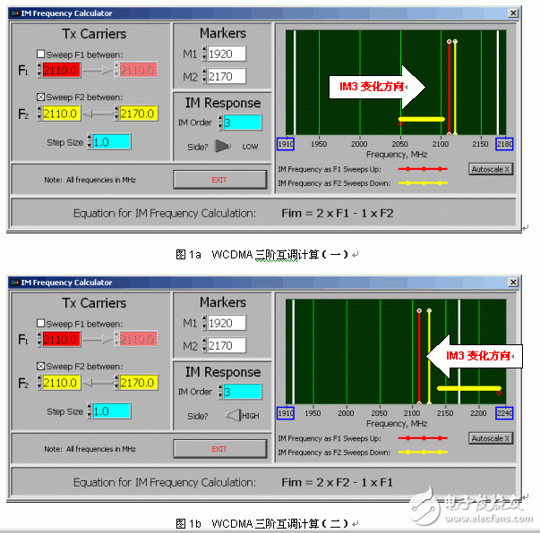
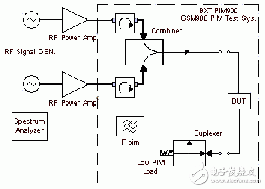
The third-order intermodulation distortion produced by two frequencies is a common problem in modern communication systems. When two (or more) carrier frequency signals in the system pass through a passive component such as an antenna, cable, filter, and duplexer, due to unreliable mechanical contact, soldering and surface oxidation, etc. Non-linear factors are created at the junction of different materials, just like a mixing diode. The further intermodulation products further produced by the two carrier signals (F1 and F2) and their second harmonics (2F1 and 2F2) are third-order intermodulation distortions (2F1-F2 and 2F2-F1). A typical indicator of the third-order intermodulation product (IM3) is that when two +43 dBm carrier frequency signals are simultaneously applied to the device under test (DUT), the resulting IM3 value is no more than -110 dBm, which is -153 dBc. Third-order intermodulation distortion can degrade the performance of the communication system. Excessive third-order intermodulation products in the transmitted signal can interfere with other receivers, eventually causing the receiver to malfunction. Often, designers are more concerned with intermodulation testing of active devices. However, with the development of communication systems and the improvement of system quality, the measurement of passive intermodulation has also been paid more and more attention. In GSM900/1800 and 800MHz CDMA communication systems, the third-order intermodulation products produced by the transmit band fall into their respective receive bands. The WCDMA frequency band is different, and the third-order intermodulation products generated by the transmission frequency band (2110MHz~2170MHz) will not fall into its own receiving frequency band (1920MHz~1980MHz), but will fall into the transmitting frequency band. This phenomenon can be verified by the following mathematical calculations. The third-order intermodulation product FIM3=2F1-F2, where F1=[2110, 2170], F2=[2110, 2170]. To prove FIM3≠[1920, 1980], just find the range of values ​​of FIM3, and then see if this set has an intersection with [1920, 1980]. The range of values ​​of FIM3 is required. The key requirements are the minimum value FIM3(min) and the maximum value FIM3(max): FIM3(min)=2F1min-F2max=2&TImes;2110-2170=2050; FIM3(max)=2F1max-F2min =2&TImes; 2170-2110=2230. It can be seen that FIM3=[2050, 2230] has no intersection with [1920, 1980], that is to say FIM3≠[1920, 1980]. The calculation tool can also characterize the trend of the third-order intermodulation in the WCDMA band. This trend is consistent with the above calculation results, as shown in Figure 1. Figure 1a shows the trend of IM3 from 2050.0 to 2110.0MHz when F1 = 2110.0MHz and F2 changes from 2110.0MHz to 2170.0MHz; Figure 1b shows that when F1 = 2110.0MHz, F2 changes from 2170.0MHz to 2110.0MHz. When IM3 changes from 2230.0 to 2110.0MHz. From the above situation, it can be found that no matter how F1 and F2 change in the range of 2110.0MHz to 2170.0MHz, IM3 will not fall into the 1920.0MHz~1980.0MHz frequency band, but will fall to the 2050.0MHz~2170.0MHz frequency band. In addition, the seventh-order intermodulation of the WCDMA system will fall into its receiving frequency band, such as IM7=4&TImes; 2110-3&TImes; 2170=1930MHz, and this issue will be discussed separately. In a WCDMA system, if a passive intermodulation signal of -110 dBm is generated in the transmit band, that is, an interfering signal, this may have an impact on the system because this value is already greater than the minimum amplitude of the useful signal in the system. In GSM900/1800 and 800MHz CDMA communication systems, the IM3 generated by the transmit band will fall into the respective receive band. In the passive intermodulation measurement system of these three systems, a duplexer and a filter are usually used to extract the IM3 value. Figure 2 shows a typical two-port passive intermodulation measurement system (BXTPIM900) for the GSM900 receive band. When F1 and F2 pass through the DUT, the output of the DUT has four frequency components F1, F2, 2F1-F2, and 2F2-F1, where F1 and F2 are directly absorbed by the high power low intermodulation load, and 2F1-F2 and 2F2- F1 is extracted by the duplexer, and the filter is used to further filter out F1 and F2 to improve the dynamic range of the spectrum analyzer. Since the third-order intermodulation products all fall into the receiving frequency band, standard duplexers and filters can be used. Figure 2BXTPIM900 two-port passive intermodulation measurement system The WCDMA frequency band is different. From the above analysis, we find that the IM3 value generated by the transmitting frequency band (2110MHz~2170MHz) falls to the transmitting frequency band, that is, the IM3 value is close to F1 and F2. In this case, the duplexer cannot be used to extract the IM3, but other methods are used. Figure 3 refers to the IEC recommended emission band IM3 test method. The two 46dBm CW signals are respectively combined into a transmission line through the combiner and applied to the DUT. The synthesized signal is absorbed by the DUT and then absorbed by a low intermodulation load. The -30dB signal is coupled by the directional coupler. Adjust the bandpass filter and test the allowed IM3 values ​​on the spectrum analyzer. From the test principle and method, the test of passive intermodulation is not complicated, but it is not easy to complete accurate test. When building a test system, pay attention to every aspect of the system. (1) Power amplifier. In some PIM test systems, a 43dBm amplifier is typically used. However, in WCDMA systems, due to the peak-to-average power ratio of WCDMA signals, higher requirements are imposed on the system's transmit power, that is, passive components in WCDMA systems operate at higher RF power levels. Therefore, the power in the WCDMA passive intermodulation measurement system should be as large as possible, but due to the limitation of the amplifier cost and the combiner power capacity, a power amplifier of 46-47 dBm is usually used.
We are a professional manufacturer in the cabling solutions supplies in Ningbo, we could offer the Patch Panel in 8-48 ports, cat5e, cat6 cat6a specification; Metal or plastic Cable Management with brush; the Keystone Jack in UTP and STP style; surface wall mount box in blank, cat5e cat6 or other mount box; the RJ45 Modular Plug in 8P8C, cat5e, cat6, cat7 basing on UTP and STP Style; 86 type, UK type, France, type, German type, USA type Face Plate in 1 port to 8 ports; Stripper and Crimping tool and tool kits, cable tester for RJ11 RJ12 RJ45, HDMI,USB connector; cabling solution accessories like as cable tie, Cabinet screw, LSA module frame, indoor and outdoor distribution box, fiber optical distribution box and patch panel.
We have more 6 staffs in QC team, and 4 staffs in technical division to keep the high quality of products and service to our customers.
CAT5E Patch Panel,STP Patch Panel,24 Ports Patch Panel,keystone patch panel NINGBO UONICORE ELECTRONICS CO., LTD , https://www.uniconmelectronics.com
