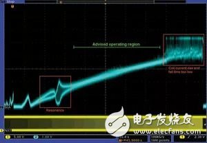
In optimizing the design of motion control systems based on stepper motors, engineers must consider factors such as cost, performance, efficiency, unexpected feedback challenges (such as mechanical resonance), and development time. Modern motor control systems face the challenge of operating in a variety of adverse environments, and the overall efficiency of traditional solutions is often limited by the worst-case conditions encountered by the entire system. Adaptive control algorithms are essential to extract the maximum efficiency of an optimized electromechanical system. System mapping If you want the highest efficiency, you must map the boundary conditions of the entire electromechanical system. All system variables must be considered: temperature, mechanical degradation, acceleration, speed, supply voltage, and so on. The system architecture also has an impact on it. In open-loop systems, it is often necessary to excite the motor with worst-case current drive and speed profiles, so we can assume that efficiency is not the primary design goal for such systems. This type of testing is very time consuming because the system must be verified at all supply voltage, temperature and speed values ​​that the motor may use to minimize the risk of resonance. Every stepper motor system has the potential to resonate, usually because it operates at (or close to) the natural frequency of the motor. Avoiding these areas is critical because resonance can cause the motor to lose motion or enter a stall condition. However, for open loop systems, determining these areas can be very difficult. Closed loop control typically takes two forms: a sensor-based system (light or Hall effect) and a sensorless system. Sensorless systems, also known as "semi-closed loop systems", typically use the voltage generated by the motor coils as feedback. Sensor-based control systems are widely used, but other changes to the sensor must be considered in mapping practice. A major advantage of sensorless systems is that they only need to read information about the physical motion of the motor. Another important advantage is the reduced system cost of closed-loop or semi-closed loop systems, while reducing the complexity of the system by eliminating the need for external sensors. Successful design requires an understanding of the characteristics of the back EMF. SLA mapping Back EMF facilitates the extraction of detailed information related to the motion of the electromechanical system and provides diagnostic data. A voltage is generated between the drive current pulses of the motor and the movement of the motor coil through the magnetic field of the motor. This information is often referred to as the speed and/or load angle (SLA) of the motor. The angular velocity of the stepper motor can be well approximated by monitoring the magnitude of the back EMF. Figure 1 shows the mapping of the SLA pins when driving a conventional stepper motor mounted in a mechanical system using the AMIS-30522 subdivided stepper motor controller. This information is collected during the sweep of the NXT input (the clock input that determines the motor excitation speed). As it moves from left to right, the frequency of the excitation increases and you can clearly see the different work areas. The ability to measure the motor characteristics of the entire system is a very powerful feature of the AMIS-305xx series—especially it can handle traditional design challenges, but before that, the system designer only analyzed the resonance performance of the motor, and It is not recognized that these areas may change once the entire mechanical device is put together. Figure 1 Simultaneously monitoring the SLA pin while sweeping the NXT pin The motor control system can continuously sample the SLA voltage, and if an abnormal situation is encountered, appropriate measures can be taken. Since the back electromotive force is proportional to the rotational speed of the rotor, it can be conveniently used to sense the external load on the output shaft and regulate the current supplied to the motor. Another area where data from the SLA pin is very useful is when the motor is about to enter the resonant region. By designing an algorithm to quickly identify this situation, the stepper motor control system can immediately accelerate through this area to reach a new safe speed. The red square on the left side of Figure 1 highlights the resonance in the system. This may be due to the actual installation of the motor, the fundamental frequency of the motor resonance between the stepped steps, or other second-order factors. These are usually commutation speed zones that need to be avoided. If ON Semiconductor's back EMF technology is used, it can be easily mapped in a matter of minutes. This will help reduce the pressure on the electromechanical system. This is important because system pressure can cause increased noise, degraded performance, and may result in reduced system reliability. The highlight of this data collection method is that the mapping process can be completed without physical changes to the system. The only sensor is the motor itself, so there is no additional mechanical complexity. The red square on the right side of Figure 1 indicates the area where the current drive exceeds the RLC time constant of the system, resulting in residual current on the motor coil. It is the "speed limit" for this particular electromechanical system. Between these two areas is the recommended motor working area. It should also be noted that the same mapping can also be used to identify stall conditions where the motor cannot be commutated (and thus cannot generate back EMF). In the system controller, this situation can only be controlled by configuring the minimum threshold between motor excitations. Use mapping data in your design Once the mapping is complete and the ideal speed profile is known, the best SLA value can be chosen. For a given system, it will represent the most efficient work point. Motor control variables such as current drive, acceleration, and speed can be dynamically adjusted to avoid problems that can compromise efficiency, such as mechanical resonance and excessive drive current. The advantage of the sensorless/back EMF method is that the feedback from the sensor is not a simple binary information, but can be used to obtain detailed diagnostic information from the motor without adding additional system complexity, allowing us to use Subtle changes in the SLA for real-time compensation to avoid lost steps.
ZGAR AZ MC Disposable
ZGAR electronic cigarette uses high-tech R&D, food grade disposable pod device and high-quality raw material. All package designs are Original IP. Our designer team is from Hong Kong. We have very high requirements for product quality, flavors taste and packaging design. The E-liquid is imported, materials are food grade, and assembly plant is medical-grade dust-free workshops.
Our products include disposable e-cigarettes, rechargeable e-cigarettes, rechargreable disposable vape pen, and various of flavors of cigarette cartridges. From 600puffs to 5000puffs, ZGAR bar Disposable offer high-tech R&D, E-cigarette improves battery capacity, We offer various of flavors and support customization. And printing designs can be customized. We have our own professional team and competitive quotations for any OEM or ODM works.
We supply OEM rechargeable disposable vape pen,OEM disposable electronic cigarette,ODM disposable vape pen,ODM disposable electronic cigarette,OEM/ODM vape pen e-cigarette,OEM/ODM atomizer device.
Disposable E-cigarette, ODM disposable electronic cigarette, vape pen atomizer , Device E-cig, OEM disposable electronic cigarette ZGAR INTERNATIONAL TRADING CO., LTD. , https://www.zgarvapepen.com