LED flashing light production tutorial
This article provides a detailed overview of LED flashing light circuits, covering three main types: single-group flashing, two-group alternating flashing, and three-group cyclic flashing. It explains the basic working principles of each circuit and includes schematic diagrams for better understanding.
The single-group flashing circuit is based on an RC oscillator. When power is applied, capacitor C1 charges through resistor RP. Initially, the voltage across C1 is too low to turn on transistor VT1, so both VT1 and VT2 are off, and the LED remains unlit. As the voltage on C1 reaches about 0.7V, both transistors switch on, causing the LED to light up. The capacitor then discharges through VT1’s emitter junction, lowering the base voltage until it drops below 0.5V, turning the transistors off again. This cycle repeats, resulting in a blinking LED. Adjusting RP to approximately 470 kΩ sets the flash rate to around one second per cycle. This simple design is highly energy-efficient, making it ideal for long-term use with small batteries, such as two AA cells, which can last over a year when the circuit is continuously active.

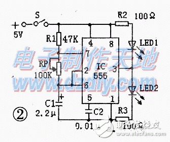
For two-group alternating flashing, the circuit uses a 555 timer IC configured as an astable multivibrator. Upon power-up, the capacitor C1 starts charging through R1 and RP. At first, the voltage at pin 2 is below 1/3 Vcc, so the output (pin 3) goes high, lighting LED2 and turning off LED1. As C1 charges to 2/3 Vcc, the output switches to low, turning on LED1 and off LED2. This continuous charging and discharging creates a periodic oscillation, resulting in alternating LED flashes. The frequency is calculated using the formula f = 1.443 / [(R1 + 2RP) × C]. The 555 IC operates between 4.5V and 18V, and with a 5V supply, current-limiting resistors of 100Ω are typically used for the LEDs.
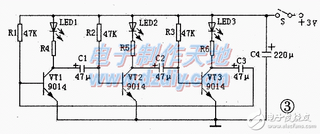
The three-group cyclic flashing circuit is a self-oscillating multivibrator using three transistors. When powered, the capacitors C1–C3 charge through the resistors and the base-emitter junctions of the transistors. Due to slight component variations, one transistor turns on first, lighting its corresponding LED while the others remain off. As the capacitor discharges, the next transistor turns on, causing the next LED to light. This cycle continues, creating a sequential lighting pattern. The timing can be adjusted by changing the values of the capacitors or resistors—larger values result in slower cycles. For higher voltages, the base resistors may need to be reduced, and higher-voltage capacitors should be used to ensure safe operation.
When building these circuits, it's important to choose the correct power supply and select appropriate current-limiting resistors. For series-connected LEDs, the resistor value can be calculated using the formula: R = (U_out - UF × N) / IF, where U_out is the supply voltage, UF is the forward voltage of each LED, N is the number of LEDs in series, and IF is the operating current. For parallel connections, the total current must be considered, and the transistor's maximum current rating (ICM) should not be exceeded. Additionally, when using high-power supplies, it’s crucial to verify that all components can handle the increased voltage and current safely.
These circuits are easy to construct, and many hobbyists prefer direct soldering for simplicity. The transistors used should have a beta value of at least 80 for stable operation. If a high-beta transistor isn’t available, two transistors can be connected in a composite configuration to achieve the same effect. Overall, these LED flashing circuits offer a great way to learn about electronics while creating functional and visually appealing projects.
Battery connector,battery holder,battery holder spring,power connector,connector
Dongguan Yiyou Electronic Technology Co., Ltd. , https://www.dsubminiature.com