LED flashing light production tutorial
This article explores the concept of LED flashing lights, which can be categorized into three main types: single-group flashing, two-group alternating flashing, and three-group cyclic flashing. Each type has its own circuit design, and this article provides detailed explanations along with circuit diagrams for each configuration.
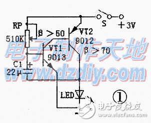
The single-group flashing light circuit is illustrated in Figure 1. It operates as an RC oscillator. When power is applied, current flows through resistor RP to charge capacitor C1. Since the voltage across C1 doesn't reach the turn-on threshold of transistor VT1 immediately, both VT1 and VT2 remain off, keeping the LED dark. Once the voltage on C1 reaches 0.7V, both transistors activate, causing the LED to light up. As C1 discharges through VT1's emitter junction, the base voltage of VT1 drops below 0.5V, turning the transistors off again. This cycle repeats, resulting in a blinking LED. Adjusting RP to approximately 470 kΩ will result in a flash frequency of about 1 second. This circuit is very energy-efficient, and using two No. 5 alkaline batteries can provide operation for over half a year or even a full year when continuously on.

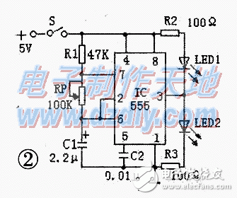
The two-group alternating flashing light circuit is shown in Figure 2. It uses a 555 timer IC configured as a multivibrator. Upon power-up, the voltage on timing capacitor C1 starts at 0V, triggering the 2-pin to go below 1/3 Vcc, which sets the 3-pin output high. At this point, LED1 is off, and LED2 is on. As C1 charges through R1 and RP, the voltage rises until it exceeds 2/3 Vcc, causing the 3-pin to switch low, turning LED1 on and LED2 off. This continuous charging and discharging between 1/3 and 2/3 Vcc creates a self-oscillating signal, making the LEDs alternate. The oscillation frequency is calculated as f = 1.443 / [(R1 + 2RP) × C]. The 555 IC can operate between 4.5V and 18V. For a 5V supply, the current-limiting resistors are typically 100Ω.

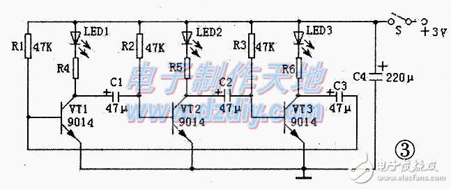
The three-group cyclic flashing light circuit is depicted in Figure 3. It’s an astable multivibrator that cycles through three groups of LEDs. When powered on, the positive voltage charges capacitors C1–C3 via resistors R4, R5, R6, and the base junctions of transistors VT1–VT3. Although the components are identical, slight variations in their values may cause one transistor to activate first. Suppose VT1 turns on first—this lights LED1 while C1 discharges through R2 and VT1’s CE junction. When VT2 turns off, LED2 remains unlit. As C2 charges to 0.7V, VT3 activates, lighting LED3. This process continues, ensuring only one group of LEDs is lit at a time. The cycle duration can be adjusted by changing the values of C1–C3 and R1–R3. Larger values increase the cycle time.

When building the flashing lights described above, it’s essential to choose an appropriate power supply voltage. Multiple LEDs can be connected either in series or parallel, but a suitable current-limiting resistor must be used. For series connections, the formula for calculating the resistor is: R = (U_out - UF × N) / IF, where U_out is the applied voltage, UF is the forward voltage of each LED, N is the number of LEDs in series, and IF is the operating current. For example, a high-brightness φ5mm white LED typically requires 3–3.2V forward voltage and 15–20mA of current. If LEDs are connected in parallel, the total current should be multiplied by the number of parallel LEDs, and the maximum collector current (ICM) of the transistor must not be exceeded. Additionally, if the power supply voltage in Figure 3 is increased, the base resistors can be reduced to 18kΩ–30kΩ, and the capacitors can be lowered to 22μF–30μF. A high-voltage capacitor should also be selected in such cases.
The circuits described are simple and can be built using direct soldering techniques. The transistors used should have a beta value of at least 80. If a high-beta transistor isn’t available, two transistors can be combined into a composite configuration to achieve similar performance. These circuits are ideal for DIY projects, offering an easy way to create dynamic lighting effects with minimal components and low power consumption.
coin battery holder,cr2032 battery holder,cr2032 holder,cr2032 socket,cr2450 battery holder,cr2450 holder,2450 battery holder
Dongguan Yiyou Electronic Technology Co., Ltd. , https://www.dsubminiature.com