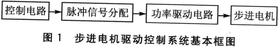
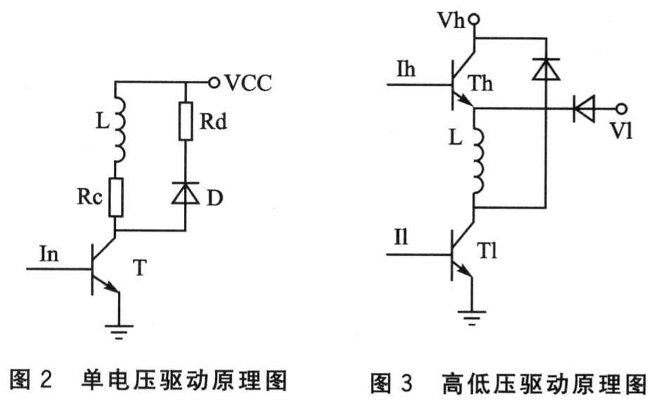
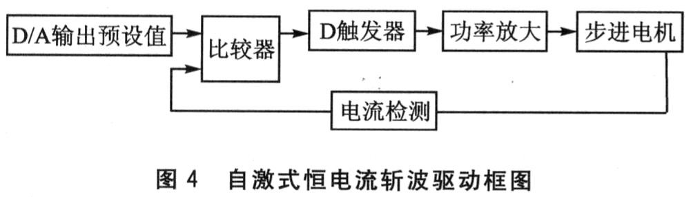
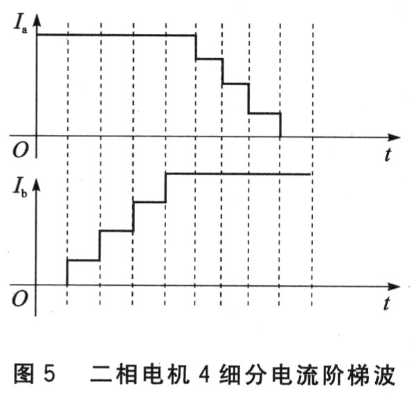
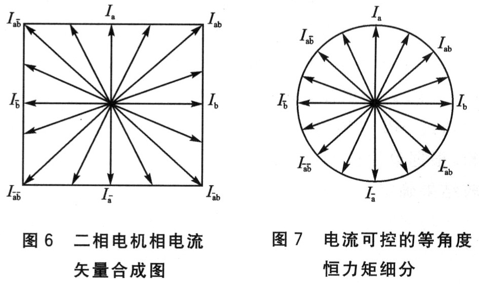
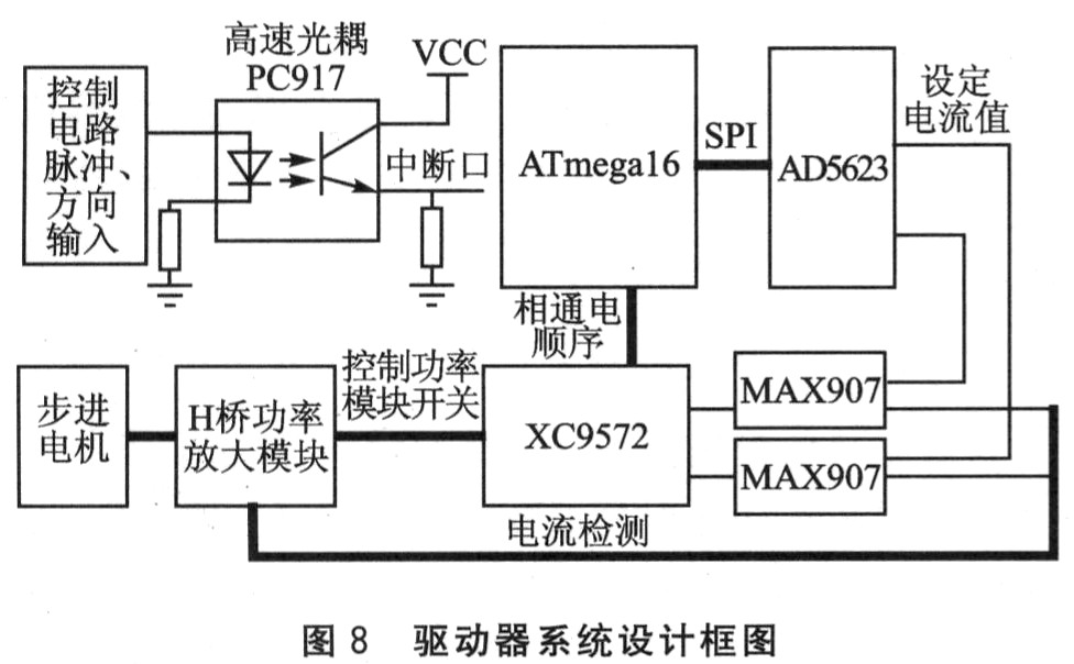
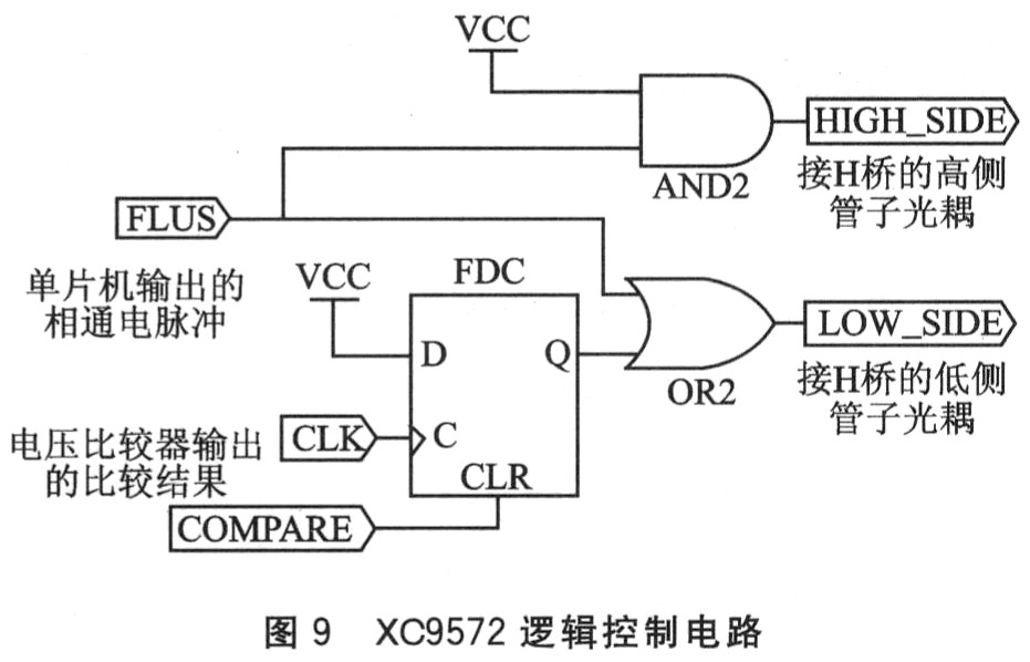
A stepper motor is an actuator that converts electrical pulse signals into angular displacement. Its main advantages are higher positioning accuracy and no cumulative position error; the unique open-loop operating mechanism reduces system cost and improves reliability compared to closed-loop control systems, and is widely used in the field of numerical control. However, the vibration and noise of the stepper motor when running at low speed are large, and resonance is likely to occur when running near the natural oscillation frequency of the stepper motor, and the output torque decreases as the speed of the stepper motor increases. Application range of stepper motor. The performance of the stepper motor depends to a large extent on the driver used. Improving the performance of the driver can significantly improve the performance of the stepper motor. Therefore, the development of high-performance stepper motor drivers is a topic of general concern. 1 Overview of stepper motor drive control system Normally, the stepping motor drive system consists of 3 parts: ①Control circuit. Used to generate pulses and control the speed and direction of the motor. ② Drive circuit. That is, the research content of this article is composed of the pulse signal distribution and power drive circuit shown in Figure 1. According to the pulse and direction signal input by the controller, provide the correct energizing sequence for each winding of the stepper motor, as well as the high voltage and high current required by the motor; at the same time provide various protection measures, such as overcurrent and overheating. ③Stepper motor. The control signal is amplified by the driver and drives the stepper motor to drive the load. 2 Comparison of stepping motor driving methods 2. 1 constant voltage driving method 2.1.1 Single voltage drive Single voltage drive means that in the working process of the motor winding, only one direction voltage is used to supply power to the winding. As shown in Figure 2, L is the motor winding and VCC is the power supply. When the input signal In is at a high level, a sufficiently large base current is provided to make the transistor T in a saturated state. If the saturation voltage drop is ignored, the power supply voltage all acts on the motor winding. When In is low, the transistor is cut off and no current flows through the winding. In order to make the winding current quickly reach the preset current when energized, a resistor Rc is connected in series; in order to prevent the winding current change rate from being too large when turning off T, and generating a large back EMF to breakdown T, a diode is connected in parallel at both ends of the winding D and resistance Rd provide a bleeder circuit for the winding current, also known as "freewheeling circuit". The advantages of the single-voltage power drive circuit are simple circuit structure, few components, low cost and high reliability. However, due to the increased power consumption after the resistor is connected in series, the efficiency of the entire power drive circuit is low, and it is only suitable for driving low-power stepper motors. 2.1.2 High and low voltage drive In order to enable the winding to reach the set current quickly when energized, the winding current will quickly decay to zero when it is turned off, and at the same time have higher efficiency, high and low voltage drive modes have emerged. As shown in FIG. 3, Th and T1 are high-voltage tubes and low-voltage tubes, Vh and V1 are high- and low-voltage power supplies, and Ih and I1 are high- and low-end pulse signals, respectively. A high voltage power supply is used at the leading edge of the conduction to increase the leading edge rise rate of the current, and a low voltage is used to maintain the winding current after the leading edge. High and low voltage drive can obtain better high frequency characteristics, but because the conduction time of the high voltage tube is unchanged, at low frequency, the winding obtains too much energy, which is easy to cause oscillation. The low-frequency oscillation problem can be solved by changing the on-time of its high-voltage tube. However, its control circuit is more complicated than a single voltage, and its reliability is reduced. Once the high-voltage tube is out of control, the motor will be damaged due to too much current. 2.2 Constant current chopping drive mode 2.2.1 Self-excited constant current chopper drive Figure 4 is a block diagram of a self-excited constant current chopper drive. The current value of the stepper motor winding is converted into a certain proportion of voltage, compared with the preset value output by the D / A converter, and the switch of the power tube is controlled to achieve the purpose of controlling the phase current of the winding. In theory, the self-excited constant current chopper drive can control the current of the motor winding to a certain constant value. However, because the chopping frequency is variable, it will cause a high surge voltage in the winding, which will cause great interference to the control circuit, easy to produce oscillation, and greatly reduce the reliability. 2.2.2 Its excited constant current chopping drive In order to solve the problem of surge voltage caused by variable self-excited chopping frequency, a fixed frequency clock can be added to the D flip-flop. This can basically solve the oscillation problem, but there are still some problems. For example: when the turn-on pulse output by the comparator is between the two clock rising edges of the D flip-flop, the control signal will be lost, which can generally be solved by increasing the clock frequency of the D flip-flop. 2. 3 subdivision drive mode This is the focus of this article and the driving method used by the system. The main advantage of subdivision drive is that the step angle becomes smaller, the resolution is improved, and the positioning accuracy, starting performance and high-frequency output torque of the motor are improved; secondly, the low-frequency vibration of the stepper motor is reduced or eliminated, which reduces The probability of the stepper motor working in the resonance zone. It can be said that the subdivision drive technology is a leap in the stepping motor drive and control technology. Subdivision driving means that instead of passing or cutting off the entire current of the winding each time the pulse is switched, only a part of the current in the corresponding winding is changed, and the resultant magnetic potential of the motor only rotates a part of the step angle. During subdivision driving, the winding current is not a square wave but a step wave, and the rated current is stepped input or cut. For example: the current is divided into n steps, and the rotor needs n times to turn through a step angle, that is, n subdivision, as shown in Figure 5. The general subdivision method only changes the current of one phase, and the current of the other phase remains unchanged. As shown in Figure 5, Ia remains unchanged from 0 ° to 45 °, and Ib increases gradually from O; from 45 ° to 90 °, Ib remains unchanged and Ia gradually changes from the rated value to 0. The advantage of this method is that the control is relatively simple, and it is easy to implement on hardware; however, from the current vector synthesis diagram shown in Figure 6, it can be seen that the amplitude of the synthesized vector is constantly changing, and the output torque is also constantly changing, resulting in a lag angle. Constantly changing. When the number of subdivisions is large and the micro-step angle is very small, the difference in lag angle change is already greater than the micro-step angle of the required subdivision, making subdivision practically meaningless. This is the shortcoming of the commonly used subdivision method. Is there a way to keep the amplitude unchanged when the angle of the vector changes? From the above analysis, it is impossible to change the current of a single phase, then change the two phases at the same time. What about the current? That is, Ia and Ib change simultaneously with a certain mathematical relationship to ensure that the amplitude of the synthesized vector remains unchanged during the change. Based on this, this paper establishes a driving method of "equal-angle constant torque subdivision with adjustable rated current" to eliminate the problem of lag angle caused by the constant change of force distance. As shown in FIG. 7, as the angle of the combined vector of the two-phase currents Ia and Ib of A and B continuously changes, its amplitude is always the radius of the circle. The following introduces the mathematical model where the amplitude of the synthesized vector remains unchanged: when Ia = Im · cosx, Ib = Im · sinx (where Im is the current rated value, Ia and Ib are the actual phase currents, and x is determined by the number of subdivisions ), The resulting vector is always the radius of the circle, which is the constant force distance. Equal angle refers to the same angle of rotation of the combined force arm every time. Adjustable rated current means that it can meet the requirements of various series of motors. For example, the rated current of 86 series motors is 6 to 8 A, while the 57 series motors generally do not exceed 6 A. The drive has a variety of gear currents to choose from. The subdivision is a subdivision of the rated current. In order to achieve "adjustable constant current with equal angle and constant current", in theory, as long as the current of each phase can meet the above mathematical model. This requires that the current control accuracy is very high, otherwise the vector angles synthesized by Ia and Ib will have deviations, that is, the step angles are not equal, and the subdivision has no meaning. The design scheme of the driver based on this driving method is given below. 3 Overall design scheme of two-phase stepper motor driver 3.1 Block diagram of system design As shown in Figure 8, the signal of the control board is connected to the interrupt port of the single-chip microcomputer through the optocoupler isolation. According to the received pulse signal, the single-chip microcomputer performs pulse signal distribution, determines the power-on sequence of each phase, and connects with the D flip-flop in the CPLD; at the same time, according to the current value and subdivision number set by the user, the D562 A / D converter is connected through the SPI port. Communicate to get the set current value (actually the voltage value corresponding to the current). The output value of the AD5623 is the voltage value corresponding to the expected current. It must be compared with the voltage value corresponding to the current detected from the power module, and the comparison result should be connected to the D flip-flop CLR pin in the CPLD. CPLD is connected to the dial switch of current and subdivision setting, and the obtained value is transmitted to the single chip through the SPI port; the control logic with D flip-flop as the core, according to the power-on sequence of each phase of the single chip and the comparison result of the comparator MAX907, determine each Power switch. The power drive module is directly connected to the motor to drive the motor. Using 8 MOS tubes IRF740 to form 2 H-bridge bipolar drive circuits. The IRF740 can withstand a maximum of 400 V voltage and 10 A current, the switching transition time will not exceed 51 ns, and the value of the tube conduction voltage Vgs ranges from 4 to 20 V. 3.2 Subdivision of key technical solutions The essence of the "Equal Angle Constant Torque Subdivision with Adjustable Rated Current" driving method is constant current control. The key is the precise control of the current, which must meet the following conditions at the same time: ①The current value output by the D / A converter must be quite close to the expected value, and the conversion speed should be fast. This system adopts AD5623 of ADI Company, 12-bit precision, is divided into 4 096 levels, meets the high precision requirements of 200 subdivisions; 2 D / A outputs meet the requirements of two phases; SPI port communication, frequency up to 50 MHz, established Fast time, single voltage power supply, simple connection. ② The detected current must accurately reflect the phase current at this time. Since the phase current of the motor is usually large and the voltage is high, it is difficult to detect. Commonly used detection methods are external standard small resistance, simple circuit, but the interference is relatively large, and the accuracy is relatively poor; Hall sensor detection is accurate, the interference is small, and the connection is not complicated, so the driver uses a Hall sensor. ③ The resolution of the comparator should be high and the conversion speed should be fast. The settling time of MAX907 is only 12 ns, and the comparison voltage can be detected as long as the difference is 2 mV (maximum does not exceed 4 mV), and the response is very sensitive. ④The logic circuit that controls the power tube switch should have a high real-time performance, to ensure that the phase current makes small fluctuations above and below the set current, so as not to cause surges and interfere with the control circuit. This article uses Xilinx's CPLD chip XC9572. The control circuit with D flip-flop as the core is all completed by CPLD. CPLD replaces various discrete components. The structure is simple and the connection is convenient. 9 is a logic diagram of the control circuit. As shown in Figure 9, when the comparison result is low (the detected current is greater than the set current), the D flip-flop output is 1, the OR gate outputs a high level, the tube is turned off, and the current becomes smaller; when the current is detected When the current is less than the set current, the tube is turned on, thereby ensuring that the phase current fluctuates slightly above and below the set current. Conclusion In this paper, the drive method of "equivalent constant-angle constant torque subdivision with adjustable rated current" is established, and based on this method, a two-phase hybrid stepper motor driver is designed and implemented, with a maximum of 200 subdivisions. 5 A / phase to 8 A / phase is adjustable and can drive stepper motors from 24 series to 86 series. Practical application proves that this method basically overcomes the shortcomings of traditional stepper motors with low-speed vibration and large noise. The torque of the motor is kept constant in a larger speed range, which improves the control accuracy, reduces the chance of resonance, and has a very good Stability, reliability and versatility, and simple structure.
Led Tube is also called LED light pipe, Led Fluorescent Tube, LED fluorescent lamp. The light source use LED as a light body. In general market, T5 and T8 are common use kinds. And 0.6M, 0.9M, 1.2M is common use size. The advantage of it is not produce noise, slow down the lights, no flicker, protect the eyes, versatility, long life, rich colors.
Led Tube Mini Led Tube,Led Tube Light,Led Fluorescent Tube,Led Light Tube Zhongshan Laidi Lighting Co.,LTD , http://www.idealightgroup.com