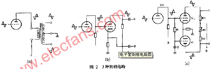
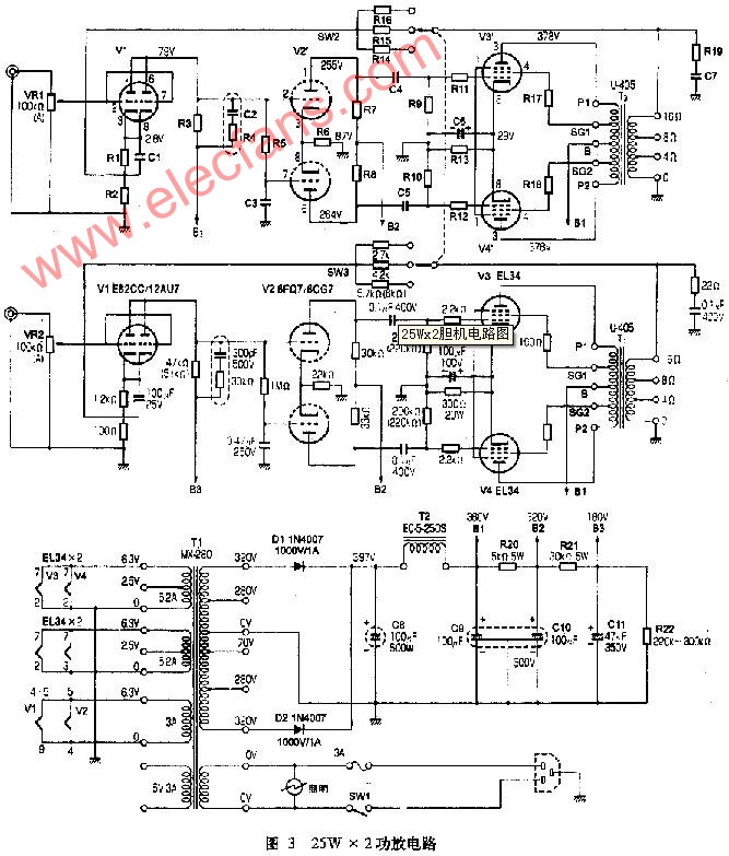
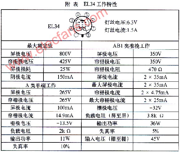
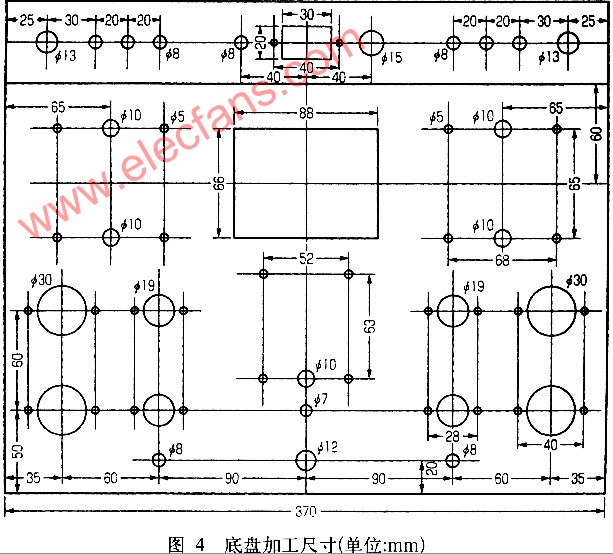
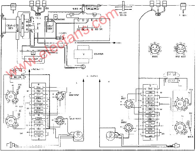
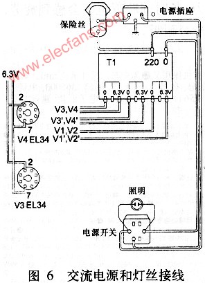
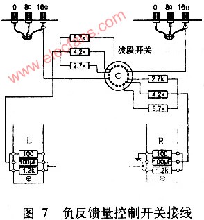
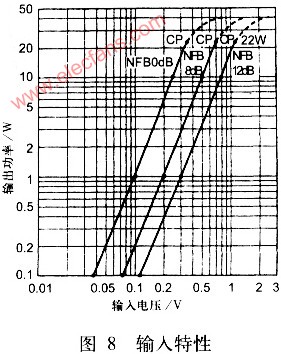
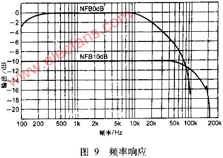
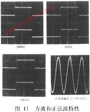
Due to the limitations of the characteristics of the tube device itself, the output power of amateur amplifiers is generally not too large, especially when using single-ended output amplifiers, the output power is smaller, usually only a few watts, generally not more than 10W. For a 10W power amplifier, it can often only provide an average operating power of l ~ 2W. Because when high-fidelity playback is performed, due to the large dynamics of the program source, the peak power at an average power of l ~ 2W has exceeded 10W, which increases the playback distortion, especially when using a speaker with lower sensitivity. More serious. It is stipulated in the minimum performance requirements of the International Electrotechnical Commission (IEC) for high-fidelity household audio power amplifiers. The rated output power of the power amplifier should be ≥10W. It can be seen from this that if you want to better enjoy various music programs including large symphonies and other tracks, a 10W × 2 power amplifier is the minimum requirement. Generally speaking, the rated power of 20 ~ 30W × 2 can achieve the basic goal of high-fidelity playback. This article details the production of a 25W × 2 power amplifier for imitation by amplifier enthusiasts who need a larger output power. One. basic structure The output power of the tube amplifier mainly depends on the output tube model and the circuit program used. As far as the circuit program is concerned, to increase its output power exponentially, two methods are usually adopted. For single-ended Class A amplification, two output power tubes can be used in parallel, as shown in Figure 1 (a). Compared with single-tube operation, under the premise that the operating voltage remains unchanged, the screen current increases by a factor of 1, and the output power also increases by a factor of 1, while the input voltage and distortion remain unchanged. In addition, due to the parallel connection of the two tubes, the internal resistance is reduced by half, and the load resistance is also reduced by half. Therefore, as long as the current capacity of the power supply is increased and the primary impedance of the output transformer is reduced by half, it is easy to change the single-tube A-type output to a double-tube parallel A-type working mode. In fact, the primary impedance of the output transformer does not have to be strictly reduced by half, and it can already obtain a much larger output power than the single-tube operation. For example, when 300B is used for single-ended Class A operation, the primary impedance of the output transformer is 3 to 3.5 kΩ. When changing to double-tube parallel A-type work, the primary impedance of the output transformer can be 1.5 ~ 1.6kΩ, at this time the output power is roughly twice that of a single tube. However, if there is no ready-made output transformer with an impedance of 1.5 to 1.6 kΩ, an output transformer with a primary impedance of 2 to 3 kΩ can also be used instead. When designing the circuit at 350V, the actual voltage of the screen to ground is about 350 + 30 = 380 (V). According to the measured data in Figure 3, the output stage cathode (to ground) voltage is 29V, so the static current of the two tubes is 29V / 300Ω = 96mA, the current of each tube is 48mA, and the actual screen loss of the EL34 is 350V × 48mA = 16.8W . This accounts for only 67% of the EL34's maximum screen loss (25w). Due to the large margin left, it is very beneficial for extending the working life of the tube. The inverter stage (V2) uses a cathode-coupled inverter circuit. As can be seen from Figure 3, the two tube screens use fixed resistors, but the resistance is slightly different. R7 takes 30kQ and R8 takes 33k Q, which can be eliminated Balance adjustment. If the producer has a signal generator and an oscilloscope, you can adjust it as follows. First change R8 to 30kΩ, then connect a variable resistor (5kΩ) to the screen circuit of V2 (the next tube); then input a 1kHz sine signal, and observe the waveform of the upper and lower output signals with an oscilloscope. Fine-tune the variable resistor to make the amplitude of the two waveforms equal; finally, use fixed electricity with similar resistance value. Of course, the output power at this time has been reduced to less than twice that of the single tube, but it is still significantly higher than the single tube. Output. Similarly, the output impedance is also low. Another way to increase the output power is to use push-pull output, as shown in Figure 1 (b). Since the working state of the push-pull output can be set to class A, class AB and class B, so in terms of output power, it can reach l to 2 times when single-ended output. For Class A push-pull with less distortion, it is generally l times larger than single-ended output power. In fact, in push-pull operation, for the AC signal, the two tubes work in series, so the primary impedance of the output transformer is l times that of the single-ended output, and the output power is also roughly doubled. Compared with the single-tube single-ended output, the output power of the double-tube single-ended output and the push-pull output are about doubled. However, the push-pull output is not only efficient, but because the DC direction of the two tubes flowing through the primary side of the output transformer is opposite, the DC magnetic flux cancels each other out, and there is no need to leave an air gap in the core of the transformer under the same conditions. The inductance is much higher than that of single tube, which is beneficial to simplify the structure. In addition, the push-pull output transformer has the effect of canceling the power supply ripple, thus reducing the requirement for power supply filtering. Finally, the push-pull circuit can also cancel even harmonics, the distortion is significantly lower than the single-ended output. The disadvantage of the push-pull circuit is that the tubes need to be paired, and two drive signals with the same amplitude and opposite phases are required, that is, an inverter circuit is required. In addition, the two primary windings of the output transformer should be as symmetrical and balanced as possible in terms of number of turns, DC resistance, leakage inductance, and distributed capacitance. If the better this is done, the advantages of the push-pull circuit will become more obvious. The inverting circuit necessary for the push-pull output has three common methods shown in Figure 2. Figure 2 (a) shows the inverter inversion, no active devices are required, the circuit is simple, the inverted signal waveform is good, the distortion is low, the output impedance is low, it is not easily affected by the output stage gate current and the driving ability is strong, but this requires a good performance Input transformer. Figure 2 (b) shows the reversed load of the screen and the negative load. Since the signals taken from the load resistance and the cathode resistance of the screen are exactly inverted, as long as the screen resistance is equal to the cathode resistance, plus 100% through the cathode resistance , The current negative feedback of this stage, can obtain the inverse drive signal with the same amplitude from the screen and cathode. The circuit has less distortion and gain ≤1, so it requires a sufficiently high gain in the previous stage, or a push-pull voltage amplification stage is added after it, otherwise it is not easy to obtain a sufficiently large power output. Neither of the above two inverter circuits needs to be adjusted, and the gain is basically unity. Figure 2 (b) is most common in amateur production in China. Figure 2 (c) shows the cathode-coupled inversion, which is characterized in that it can obtain a higher gain while inverting the input signal. However, the amplitude of the inverted signal output by this circuit is not strictly equal, which means that balance adjustment is required, which is an inconvenience for amateur production, so this inverted circuit is more common in commercial machines produced by manufacturers. In the past, there are not many applications of this kind of inverter circuit in amateur production in China. For this reason, there should be a general understanding of its working principle, please refer to Figure 2 (c). The input signal is firstly amplified by the first-level voltage (v1), and then enters V up and V down for inversion and amplification. The output signal of V1 directly enters the upper gate of V and extracts the amplified signal from its screen as the drive signal of the push-pull amplifier stage. Obviously, this signal is inverted with its gate input signal. In other words, the working condition on V is exactly the same as the general voltage amplification stage. The other push-pull drive signal is obtained from the V bottom panel. However, the working configuration under V is different from that on V. Its cathode is connected to v. The cathode of the two means that the two share a cathode resistance. Its gate is connected to the upper gate of V through a high-value resistor R (1 MΩ), and at the same time, the gate under V is grounded through a large-capacity capacitor C (0.47 μF). In other words, the gate under V is grounded for AC, that is, the gate under V works in the grounded state, and the input signal is taken from the cathode resistance on V and injected by the cathode. In this way, V works in the cathode-grounded amplification state, the output signal of the screen is opposite to the input signal of the gate, and the signal on the cathode resistance is in phase with the input signal of the gate, that is, inverse to the output signal of the screen. Under V, the gate is grounded and amplified, and its screen output signal is in phase with the cathode input signal, that is, it is inverse to the output signal of the screen on V, thus at V. , V under the screen can take out the opposite phase inversion signal. As for the amplitude between the inverted signals, because the amplification amounts in the two working states are not the same, so when the two tubes take the same screen resistance, the output signal amplitude is not the same. It is usually amplified when the cathode is grounded. Therefore, as long as the screen resistance under V is appropriately increased, that is, a variable resistor VR is connected in series with R2 in FIG. 2 (c) for fine adjustment, the inverted signal with the same amplitude can be obtained. two. Practical circuit Fig. 3 is the electrical schematic diagram of a 25W × 2 power amplifier designed according to the above circuit structure, in which the power supply part is shared by the left and right channels. It can be seen from the figure that the entire amplifying part is composed of the input voltage amplification (V1), inverting (V2) and output (V3, V4). The output stage adopts EL34. This tube has stable performance and sound quality is also very good, and it is easy to buy on the market, without worries about out of stock. The attached table is the main application characteristics of EL34. It can be seen from the table that when EL34 is used for single-ended Class A amplification, the maximum output power of the screen load impedance at 2k Q is l 1 w (distortion rate 10%). When it is used for push-pull amplification, the maximum output power of the screen-to-screen load impedance of 3.8kΩ can reach 36W (distortion rate 5%). Since the maximum output power of this machine is about 22 ~ 25W, basically you can choose the working parameters in the AB state in the table, that is, the screen voltage is 350V, and the screen current is slightly larger (about 48mA), which is helpful to reduce distortion. It should be pointed out here that the grid or curtain grid voltages in the table are relative to the cathode potential. Since this output stage uses a cathode self-bias circuit, that is, the voltage drop (about 30V) flowing through the cathode common resistor R13 of the two tube screens is used as the bias voltage of the output stage, so the screen electrode voltage as the resistance in the table can be substituted. Variable resistance is sufficient. Since the inverter stage of this machine has a large gain, and the output power of this machine is not too large, the gain requirement of the input voltage amplifier stage is not high, and it is enough to use a first-stage transistor voltage amplifier. It is also possible to use a dual transistor to share the voltage amplification of the left and right channels, but for the isolation between the left and right channels, a dual transistor is connected in parallel for voltage amplification of one channel. Power amplifiers using multi-pole transistors as the output stage usually have a certain overall negative feedback to reduce the output impedance and increase the damping coefficient (DF) due to the high internal resistance. In general, the amount of negative feedback is large, the damping coefficient is low, and the power amplifier has a strong braking capacity for the speaker. However, for a specific speaker, the damping coefficient is too high or too low is not the best. For this reason, the amount of negative feedback of this unit can be changed by the band switch. The amount of negative feedback can be selected as 8dB, 10dB and 12dB, respectively, which is determined by the user according to the actual use. Due to the relatively low power requirements of push-pull amplification, the power supply of this unit is also quite simple. In order to improve the rectification efficiency, a crystal diode is used instead of the traditional tube rectification. three. Production and debugging The chassis can be designed and processed after purchasing large main components such as power supply and output transformer. Figure 4 is for reference. It should be noted that this size only gives the relevant dimensions of the upper part of the chassis and the rear side panel, both sides and the front side panel are not drawn, and the reader can decide its processing size. The power filter choke and power transformer are in the center of the chassis, and the output transformer is on the left and right. The left and right sides of the rear side panel are the input socket and the speaker terminal; the middle is the power socket, and the two sides are the fuse holder and the band switch that controls the negative feedback amount. The power switch is installed in the center of the front of the chassis, and on both sides is the volume control of the left and right channels. The output transformer is U-405 (ISO) of Hirata Electric Works, Japan. If it is not available, it can also be commissioned according to the following requirements: rated output power 60W, primary side (screen-to-screen) impedance 5k Q. The primary impedance is 4Q, 8Ω and 16Ω. The maximum DC current (balanced) on the primary side is 270mA, and the unbalanced current is 7mA. The maximum inductance on the primary side is 380H and the minimum is 160H. Frequency characteristic 4Hz ~ 80KHz. Attached grid taps. Figure 5 is a schematic diagram of the layout of the main components and physical wiring of the chassis. There is a "ground point" on the left side of the power transformer. Here the chassis must be polished and cleaned, and securely fixed with screws with toothed welding pads to ensure that it is electrically grounded. All wiring that passes through the chassis (output transformer lead, B power cord, curtain grid lead, etc.) needs to be protected by a bushing. Use shielded wires for the input leads (see Figure 5), and use other plastic wires for the other leads. Figure 6 is a schematic diagram of AC power supply and filament wiring. Figure 7 is a schematic diagram of the wiring of the negative feedback control switch. Six negative feedback resistors are directly installed on the band switch. It should be added that the cathode resistance and bypass capacitor (3 () 0t2 / 20W enamel resistance and 100μF / 100V) of the left and right channel output stage in Fig. 5 indicate that they are installed near the EL34, and actually installed near the output terminal, especially The 300Ω / 100μF of the R channel is installed between 100μF × 2 and 100μF / 500V in front of the output terminal. After the installation is completed and checked for correctness, the tube can be inserted into the power-on test, and pay attention to whether there are any abnormal conditions such as smoke and odor. If there is no abnormal situation, a multimeter can be used to measure the EL34 cathode-to-ground voltage, which should be 28-30V, indicating that the output stage is working properly, and then measure the voltages of each electrode of 12AU7 and 6CG7, which should be close to the voltage value shown in Figure 3. This shows that the circuit installation is correct and the work is basically normal. Then first disconnect the negative feedback wiring, connect the speaker and CD player to listen. Since negative feedback has not been added, the sound may not be ideal. Restore the negative feedback wiring after shutting down, and then power on to listen. If self-excitation occurs as soon as power is turned on, it means that negative feedback is mistakenly connected to positive feedback. For this reason, the power supply should be disconnected and the wiring of the primary side Pl, SG1 and P2, SG2 of the output transformer can be exchanged. Power on the test again and change the amount of negative feedback, you can hear the sound quality will change, so far the installation is complete. four. Performance First of all, the residual noise of this unit is 0.3mV when the amount of negative feedback is 12dB. It should be said that the data is not very good. However, even when playing with large speakers, there is no hum. Figure 8 is the input characteristics of the machine. The clipping power at different negative feedback amounts is basically 2 2 W. When the negative feedback value NFB = 8dB, the actual measured value of the maximum output voltage when clipping on the 8Ω terminal on the secondary side of the output transformer is 14V (1kHz), which is equivalent to U2 / RL = 14V × 14V / 8 Ω = 24. 5W, the input sensitivity is about 0.74V. It can be said that the expected design requirements are met. Figure 9 shows the frequency response, 30Hz ~ 15kHz (one ldB) when there is no feedback, and it extends to 10Hz ~ 70kHz (one ldB) when the negative feedback of Force II 10dB is 10dB, and it only drops 2dB at 100kHz. Obtaining such a good frequency response is mainly due to the wide frequency response of the output transformer. Fig. 10 is the total harmonic distortion (THD) characteristic when the negative feedback amount of this unit is 8dB and 12dB respectively. When NFB = 12dB, the output power is only 0.02% at 1W (1kHz), 0.3% at 5W, and 2% at 22W. The output impedance of this machine is 1.44 Q (1kHz), and the damping coefficient when the load is 8Ω is 8Ω / 1.44Ω = 5.5, which is obviously lower than the damping coefficient of the general single-ended output. Figure 11 shows the waveforms at 200Hz, 1kHz and 10kHz square wave response (upper input square wave and lower output square wave) and 22.5W sine wave (1kHz, NFB = 12dB), which are very good. This unit is tested together with the JBL4312Mll speaker. The sound is transparent and wide. It is charming. You won't feel tired after listening for a long time. It is very durable. LED FLOWING USB CHARGING CABLE Voice Control Led Flowing Cables,Music Operated Led Flowing Cable,Shinning Micro Usb Cable Shareconn Development CO.,LTD , http://www.share-conn.com