The design uses AVR single chip microcomputer, using RS 485 technology and NTC thermal sensor technology to develop the remote temperature difference cycle controller.
1 System structure and working principle
The remote temperature difference circulation controller is mainly used for measuring and displaying the water temperature of the water tank of the split pressure solar water heater, the temperature of the collector, the temperature of the pipeline, and controlling the temperature difference circulation, auxiliary electric heating, pipeline antifreeze and parameter setting, etc. The controller is mainly composed of the host, slave, water temperature sensor, antifreeze sensor and other parts. The core of the host is ATmega16 MCU, which communicates with the slave through RS 485, displays the temperature data collected by the slave, and completes the basic function settings, and transmits the setting data to the slave; the slave also uses the ATmega16 microcontroller as the main controller to complete the data collection And control execution, the overall block diagram of the system is shown in Figure 1.

2 System hardware design
The remote temperature difference circulation controller uses ATmega16 as the core. The single-chip microcomputer has a serial interface, which can be connected to a 485 conversion chip to realize RS 485 communication. The built-in 8-bit A / D module can directly realize the A / D conversion input of 8-channel analog signals. ; E2PROM with 512 B can realize data power-off protection.
2.1 Host circuit
The main function of the host is to receive the 4-channel temperature data collected by the slave and display it on the 128 × 64 LCD; another function of the host is to complete the basic settings and then send the setting parameters to the slave. The host is mainly composed of several modules such as RS 485 communication, keyboard input, LCD display and so on.
2.1.1 RS 485 communication
Because RS 485 bus communication mode has the characteristics of simple structure, low price, appropriate communication distance and data transmission rate, it has been widely used in instrumentation, intelligent sensor distributed control, building control, monitoring alarm and other fields.
The interface chip MAX485 is used in this design, as shown in Figure 2. The chip is an RS 485 chip from Maxim Corporation. It uses a single +5 V power supply, has a rated current of 300 μA, and uses half-duplex communication. The structure and pins of the MAX485 chip are very simple, with a driver and receiver inside. The RO and DI terminals are respectively the output of the receiver and the input terminal of the driver, and only need to be connected to the RXD and TXD of the single-chip computer when connecting to the single-chip computer. The RE and DE terminals are the enable terminals for receiving and transmitting. When the RE port is logic 0, the device is in the receiving state; when the DE port is logic 1, the device is in the transmitting state, because MAX485 works in half-duplex state, so Just use the pin PD2 of the microcontroller to control these two pins. Terminal A and Terminal B are the differential signal terminals for receiving and sending respectively. When the level of the A pin is higher than B, it means that the data sent is 1; when the level of A is lower than the terminal B, it means that the data sent is 0.
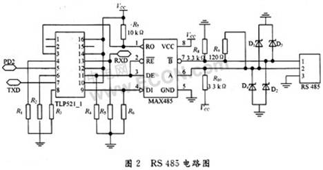
2.1.2 Anti-interference problem of RS 485 communication
The RS 485 bus has shortcomings such as self-adaptation and fragile self-protection functions. If you do not pay attention to some details, communication failures or even system failures often occur. Therefore, it is important to improve the operational reliability of the RS 485 bus.
In this design, photoelectric isolation is used first. In Figure 2, the four-in-one photocoupler TLP521_1 achieves complete electrical isolation between the microcontroller and MAX485, eliminating mutual interference and improving the reliability of the work. As shown in Fig. 2, the receiving end RXD of the single-chip microcomputer is connected to the 13th pin of TLP521_1; the RO of MAX485 is connected to the third pin of TLP521_1. In this way, when the RO has a signal input, the third pin of the TLP521_1 makes the 13th pin have a corresponding electrical signal through the photocoupling tube, thereby reducing mutual interference. The structure of TXD and PD2 is the same as RXD. Secondly, the signal limiting diodes D1 ~ D4 are added to the output terminals of RS 485, namely A and B. The voltage regulation value should ensure that it meets the RS 485 standard, D1 and D3 take 12 V, D2 and D4 take 7 V to ensure The signal amplitude is limited to -7 ~ +12 V, to further improve the ability to resist overvoltage. Taking into account the special circumstances of the line (such as the RS 485 chip of a node being short-circuited), in order to prevent the communication of other extensions in the bus from being affected, two 3.3 kΩ resistors R8 and R10 are connected in series at the signal output of MAX485 In this way, the hardware failure of the machine will not affect the communication of the entire bus. In the on-site construction of the application system project, since the communication carrier is a twisted pair, its characteristic impedance is about 120 Ω, so when designing the line, the matching end of the RS 485 network transmission line should be 120 Ω matching resistance (such as R9 in Figure 2) to reduce the reflection of the transmission signal on the line. Through the above points, you can effectively reduce the interference in RS 485 communication.
2.1.3 Output display and keyboard input circuit
The liquid crystal display uses 128 × 64 liquid crystal in OCM. The liquid crystal display module is a 128 × 64 dot matrix liquid crystal display module, which can display various characters and graphics, and can also display 4 lines of Chinese characters, which just meets the design requirements. 4-way temperature, and can be directly interfaced with CPU, with 8-bit standard data bus, 6 control lines and power lines. In this design, due to the limited reservation of the MCU interface, the connection between the LCD and the MCU uses a serial data input method. The data is connected to the fourth pin of the serial input terminal of the LCD through the MCU PA7; PA4 and PA5 are chip select signals, which are The 15th and 16th pins of the LCD; PA6 is used as a read / write enable signal and is connected to the 6th pin of the LCD. It not only has a simple interface, but also saves the I / 0 port resources of the microcontroller. The keyboard input interface uses up to 8 keys, which are implemented using a row-by-row 2 × 4 keyboard.
2.2 Slave circuit
The main function of the slave is to complete 4-channel temperature data collection and transfer these data to the host; then receive the basic setting data issued by the host to control the temperature difference cycle, RS485 communication, auxiliary electric heating, pipeline antifreeze and other functions. RS 485 communication is the same as the host computer, the following mainly introduces the temperature measurement and relay control part.
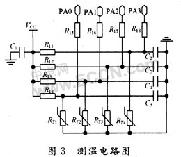
2.2.1 Temperature measurement circuit
The key to temperature measurement is to select appropriate temperature sensing elements and reasonable temperature measurement circuit parameters. A negative temperature coefficient thermistor (NTC) is selected here. It is packaged in a glass bulb, which is small in size, fast in response, low in price, and easy to install. Water temperature measurement uses NTC temperature measuring resistor TG40B503 (at 25 ℃, resistance value 50 kΩ, B value 4 050 K, glass package), after A / D conversion, the program looks up the table, control is accurate, select reasonable circuit parameters, at 0 The error can be less than 1 ℃ in the range of ~ 99 ℃, with good consistency. The temperature characteristic of NTC thermistor can generally be expressed by the following formula:
RT = RT0exp (B ï¼ TB ï¼ T0) (1)
In the formula: RT, RT0 are the resistance (unit: Ω) of the thermistor at temperature T (unit: K) and T0 (unit: K) respectively. B is the temperature coefficient of resistance of the thermistor (unit: K). The thermistor temperature measurement circuit is shown in Figure 3: RT1 ~ RT4 are the thermistors used in this design; PA0 ~ PA3 are the A / D interface of the slave ATmega16 microcontroller.
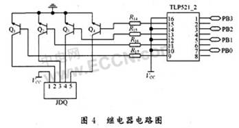
2.2.2 Relay control circuit
There are 4 channels of output power control in the system, which have the functions of slave ATmega16 single-chip microcomputer PB0 ~ PB3 port to control the temperature difference cycle, electric heating cycle, antifreeze cycle and so on. When the host presses the "temperature difference cycle" key, the host will send the signal to the slave, the slave will set RB0 high to start the manual cycle, press the "cycle" key again, the program will make RB0 output low level port, and close the manual cycle. Other functions are basically the same as "temperature difference cycle". In order to prevent the relay from possibly interfering with the control circuit part of the single-chip microcomputer, a photocoupler TLP521_2 is added between the output port of the single-chip microcomputer PB and the relay drive interface circuit, as shown in FIG. 4.
3 System software design
The software programming of the design is not complicated, and there are mainly the following modules: LCD display, RS 485 communication, A / D software filtering, row and column keyboard, relay control, etc. Here mainly introduces the processing of RS 485 communication and A / D data.
3.1 RS 485 communication format
In this design, although only two-machine communication, but for the needs of future expansion, the communication uses a polling method. The initiator of the communication is the host. Each communication is started by the host sending an instruction, and then the slave receives the instruction, and judges to execute the corresponding action according to the received instruction. There are 3 types of instructions, so 2-bit binary code is used. The codes are: 00 for query, 01 for setting parameters, and 02 for manual command transmission.
The communication process is as follows:
(1) The master sends an inquiry frame every 100 ms, and the slave returns the sensor value data frame;
(2) Setting parameters, status, etc .: The master sends setting parameter frames, and the slave returns to setting confirmation frames;
(3) If the slave does not receive the return data within the specified time, it will be resent until the slave returns correctly.
3.2 Processing of A / D data
It was found in the test that if the temperature data after A / D conversion is not processed, it is directly used for temperature difference circulation control, which will cause the relay to malfunction from time to time. Even if various filter circuits are added to the temperature measurement circuit outside the ATmega16 chip, there is still no improvement. Therefore it is inferred that the interference may come from inside the A / D conversion module. Considering that the field temperature changes slowly in this system, it is suitable to use sliding window averaging method for digital filtering. After the digital filtering method is used to average the 64 consecutive temperature data obtained after A / D conversion, the noise after A / D conversion is effectively eliminated.
4 Conclusion
The remote temperature difference circulation controller with ATmega16 as the core, using RS 485 scheme, can solve the remote communication problem well. The design scheme has the advantages of few components, low cost and good anti-interference. The controller has practical functions, accurate and reliable control, intuitive human-machine dialogue interface, and simple operation, and can meet the requirements of various split-pressure solar water heaters for temperature difference circulation and electric heating control. It has been successfully used in the control of split pressurized solar water heaters, and it can also be used for temperature difference circulation control in solar hot water projects. It has good application prospects.
Yixing Futao Metal Structural Unit Co. Ltd. is com manded of Jiangsu Futao Group.
It is located in the beach of scenic and rich Taihu Yixing with good transport service.
The company is well equipped with advanced manufacturing facilities.
We own a large-sized numerical control hydraulic pressure folding machine with once folding length 16,000mm and the thickness 2-25mm.
We also equipped with a series of numerical control conveyor systems of flattening, cutting, folding and auto-welding, we could manufacture all kinds of steel poles and steel towers.
Our main products: high & medium mast lighting, road lighting, power poles, sight lamps, courtyard lamps, lawn lamps, traffic signal poles, monitor poles, microwave communication poles, etc. Our manufacturing process has been ISO9001 certified and we were honored with the title of the AAA grade certificate of goodwill"
Presently 95% of our products are far exported to Europe, America, Middle East, and Southeast Asia, and have enjoyed great reputation from our customers,
So we know the demand of different countries and different customers.
We are greatly honored to invite you to visit our factory and cheerfully look forward to cooperating with you.


Lamp Pole
Lighting Pole, Steel Lamp Pole, Street Light Poles, Garden Lamp Post
YIXING FUTAO METAL STRUCTURAL UNIT CO.,LTD( YIXING HONGSHENGYUAN ELECTRIC POWER FACILITIES CO.,LTD.) , https://www.chinasteelpole.com