Accurate understanding of priorities is a good medicine for managing overshoot
There is a common question: "Where is the CV button or CC button of the power supply?" The answer is "No such button" because the power mode is determined by the load resistance. Once the supplied current reaches the current setting, the power supply switches from CV mode to CC mode. What exactly is the CV mode and the CC mode?
Most laboratories use DC power as a constant voltage/constant current (CV/CC) power supply. Remember that the power supply is a feedback system that allows adjustment of specific parameters. The feedback control loop of the power supply regulates the voltage under constant voltage (CV) conditions. Under constant current (CC) conditions, the feedback control loop of the power supply regulates the current.
Therefore, when you use the CV/CC power supply, it means that the power supply is running in CV mode, and the constant voltage is adjusted according to the programmed voltage setting until the load consumes enough current to reach the programmable current setting. This programmable current setting is often referred to as current limiting.
Once the supplied current reaches the current setting, the power supply switches from CV mode to CC mode. In CC mode, the power supply regulates the constant current based on the programmed current value; the voltage will begin to drop because it is no longer a regulated parameter. Conversely, if the power supply regulates a constant current in CC mode, it will continue to do so until the voltage across the load climbs to the set value. Then, the power supply will switch between CC mode and CV mode. In CV mode, the power supply will start to regulate again as described above.
Here is a common question: "Where is the CV button or CC button of the power supply?" The answer is "No such button" because the power mode is determined by the load resistance. In the case of high resistance or open circuit, the current flowing through the power supply is very small or no current is passed, and the power supply is in CV mode. Similarly, in the case of low resistance or short circuit, a large amount of current flows through the power supply and the power supply is in CC mode (Figure 1).
It should be noted that the priority mode is independent of CV and CC. The power supply in voltage priority mode can be CC or CV. Similarly, the power supply in current priority mode can also be CV or CC. The priority mode only defines the characteristics of the power supply switching from CV to CC or from CC to CV.
So what is the meaning of the priority model? The power characteristics of each priority mode will be explained below.
When the voltage priority mode voltage priority mode is activated, the initial voltage is set to 0 V and the current is set to the current setting value. Since it is in voltage priority mode, the CV loop has priority, the power supply is started at a constant voltage, and the voltage is the adjusted parameter. The voltage starts at 0 V and gradually rises to the voltage setting under the CV loop regulation, which performs well with fast voltage rise time and minimal overshoot.
If the load is high impedance, then RLOAD > (voltage setting / current setting), the power supply remains at CV, the voltage is cleanly adjusted, and current will flow into the load. As the voltage reaches the set voltage value, there is little or no voltage overshoot because the power supply makes a clean adjustment of the voltage.
In short, in voltage priority mode, the voltage exhibits good characteristics with only a small amount of overshoot. However, during the cross-conversion from CV mode to CC mode, the current may overshoot because current regulation does not take priority.
Current Priority Mode Now let's look at the current priority mode. When starting in current priority mode, the current is initially set to 0 A and the voltage is set to the voltage setting. Since the current is in the current priority mode, the CC loop has priority, so the power supply is started in CC mode and the current is the adjusted parameter. The current starts at 0 A and then gradually rises to the programmed current value under CC loop regulation for clean, good performance with fast current rise time and minimum overshoot.
If it is a low impedance load, RLOAD < (voltage setting / current setting), the power supply will remain in CC mode, and the current is cleanly adjusted. As the current reaches the set current value, there is little or no current overshoot because the power supply makes a clean adjustment of the current.
If it is a high impedance load, RLOAD > (voltage setting / current setting), the power supply will remain in CC mode, but high load impedance means that the power supply cannot make enough current to flow through the load. Any current through a high load impedance will generate a high voltage across the load, and the power supply will quickly reach the voltage setting and then switch to CV.
During the brief transition period from CC mode to CV mode, the CV loop takes priority and it has the opportunity to adjust the voltage to the voltage setting. This can result in transient voltage control instability and possible voltage overshoot (Figure 3).
Summary Although the priority mode has been implemented through analog design, modern power supplies are highly digitally controlled power supplies using digital signal processing (DSP), digital feedback loops, and FPGAs. The characteristics of the power supply, including the priority mode, can be achieved by digital technology. Therefore, no matter whether it is voltage priority or current priority, there is no difference in the power block diagram. In other words, no matter which mode is in, the power supply will not switch between different circuits or transmit signals through different paths. The digital control system commands the power supply to take different actions to achieve voltage priority or current priority.
Therefore, if you are concerned about overshoot, you can choose the appropriate priority mode. The voltage priority mode should be used when the voltage overshoot must be minimized, such as when biasing to the core of a low voltage processor or FPGA. Use current priority mode if you need to minimize current overshoot, or if your device under test is a low impedance device, such as when charging a battery or driving a system that contains large capacitance.
Most laboratories use DC power as a constant voltage/constant current (CV/CC) power supply. Remember that the power supply is a feedback system that allows adjustment of specific parameters. The feedback control loop of the power supply regulates the voltage under constant voltage (CV) conditions. Under constant current (CC) conditions, the feedback control loop of the power supply regulates the current.
Therefore, when you use the CV/CC power supply, it means that the power supply is running in CV mode, and the constant voltage is adjusted according to the programmed voltage setting until the load consumes enough current to reach the programmable current setting. This programmable current setting is often referred to as current limiting.
Once the supplied current reaches the current setting, the power supply switches from CV mode to CC mode. In CC mode, the power supply regulates the constant current based on the programmed current value; the voltage will begin to drop because it is no longer a regulated parameter. Conversely, if the power supply regulates a constant current in CC mode, it will continue to do so until the voltage across the load climbs to the set value. Then, the power supply will switch between CC mode and CV mode. In CV mode, the power supply will start to regulate again as described above.
Here is a common question: "Where is the CV button or CC button of the power supply?" The answer is "No such button" because the power mode is determined by the load resistance. In the case of high resistance or open circuit, the current flowing through the power supply is very small or no current is passed, and the power supply is in CV mode. Similarly, in the case of low resistance or short circuit, a large amount of current flows through the power supply and the power supply is in CC mode (Figure 1).
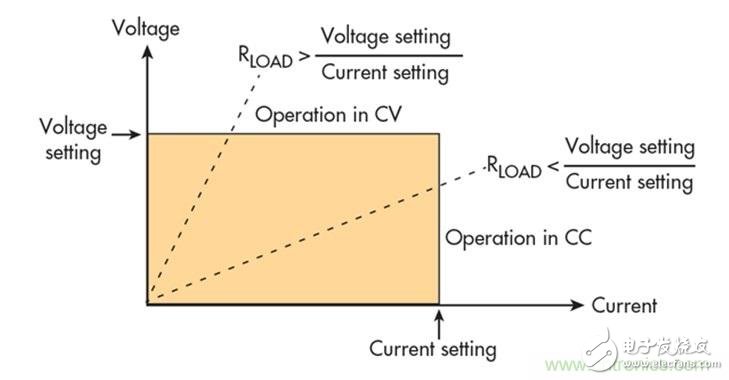
Figure 1 shows the output characteristics of the DC power supply showing the load resistance (RLOAD) value driving the CV or CC mode.
Priority mode introduces us to introduce the next concept: priority mode. In addition to the CV and CC modes, the power supply can have both voltage priority and current priority modes. The priority mode controls the characteristics of the power supply. In voltage priority mode, the voltage control loop of the power supply has priority. Most power supplies on the market today only have voltage priority and do not provide current loop priority mode. In fact, this situation is very common, and most engineers never even realize that there is a priority mode, they just expect their CV/CC power supply to have a voltage priority mode. It should be noted that the priority mode is independent of CV and CC. The power supply in voltage priority mode can be CC or CV. Similarly, the power supply in current priority mode can also be CV or CC. The priority mode only defines the characteristics of the power supply switching from CV to CC or from CC to CV.
So what is the meaning of the priority model? The power characteristics of each priority mode will be explained below.
When the voltage priority mode voltage priority mode is activated, the initial voltage is set to 0 V and the current is set to the current setting value. Since it is in voltage priority mode, the CV loop has priority, the power supply is started at a constant voltage, and the voltage is the adjusted parameter. The voltage starts at 0 V and gradually rises to the voltage setting under the CV loop regulation, which performs well with fast voltage rise time and minimal overshoot.
If the load is high impedance, then RLOAD > (voltage setting / current setting), the power supply remains at CV, the voltage is cleanly adjusted, and current will flow into the load. As the voltage reaches the set voltage value, there is little or no voltage overshoot because the power supply makes a clean adjustment of the voltage.
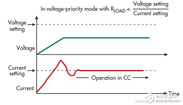
Figure 2 Voltage priority mode characteristics at startup cause current overshoot in CV to CC conversion
If it is a low impedance load, then RLOAD < (voltage setting / current setting), the voltage will start to work in CV mode, but low load impedance means that the voltage can not reach the set value. Instead, the source current quickly reaches the current setpoint, converted to CC, and the voltage will collapse. In the short transition from CV mode to CC mode, the CC loop takes priority and it takes some time to adjust the current to the current setting. This can result in brief current control instability, which further produces current overshoot (Figure 2). In short, in voltage priority mode, the voltage exhibits good characteristics with only a small amount of overshoot. However, during the cross-conversion from CV mode to CC mode, the current may overshoot because current regulation does not take priority.
Current Priority Mode Now let's look at the current priority mode. When starting in current priority mode, the current is initially set to 0 A and the voltage is set to the voltage setting. Since the current is in the current priority mode, the CC loop has priority, so the power supply is started in CC mode and the current is the adjusted parameter. The current starts at 0 A and then gradually rises to the programmed current value under CC loop regulation for clean, good performance with fast current rise time and minimum overshoot.
If it is a low impedance load, RLOAD < (voltage setting / current setting), the power supply will remain in CC mode, and the current is cleanly adjusted. As the current reaches the set current value, there is little or no current overshoot because the power supply makes a clean adjustment of the current.
If it is a high impedance load, RLOAD > (voltage setting / current setting), the power supply will remain in CC mode, but high load impedance means that the power supply cannot make enough current to flow through the load. Any current through a high load impedance will generate a high voltage across the load, and the power supply will quickly reach the voltage setting and then switch to CV.
During the brief transition period from CC mode to CV mode, the CV loop takes priority and it has the opportunity to adjust the voltage to the voltage setting. This can result in transient voltage control instability and possible voltage overshoot (Figure 3).
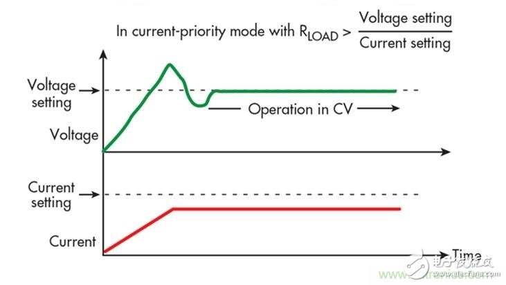
Figure 3 Current priority mode characteristics at startup can cause voltage overshoot during CC to CV conversion
In short, in current priority mode, the current exhibits good characteristics with only a small amount of overshoot. However, when switching from CC mode to CV mode, the voltage may overshoot because voltage regulation does not take priority. Summary Although the priority mode has been implemented through analog design, modern power supplies are highly digitally controlled power supplies using digital signal processing (DSP), digital feedback loops, and FPGAs. The characteristics of the power supply, including the priority mode, can be achieved by digital technology. Therefore, no matter whether it is voltage priority or current priority, there is no difference in the power block diagram. In other words, no matter which mode is in, the power supply will not switch between different circuits or transmit signals through different paths. The digital control system commands the power supply to take different actions to achieve voltage priority or current priority.
Therefore, if you are concerned about overshoot, you can choose the appropriate priority mode. The voltage priority mode should be used when the voltage overshoot must be minimized, such as when biasing to the core of a low voltage processor or FPGA. Use current priority mode if you need to minimize current overshoot, or if your device under test is a low impedance device, such as when charging a battery or driving a system that contains large capacitance.
150 Watt Solar Panel,Suntech Mono Solar Panel,Mono Cell Solar Panels,Lg Mono Solar Panel
Zhejiang G&P New Energy Technology Co.,Ltd , https://www.solarpanelgp.com