Simple digital frequency meter circuit diagram
**Simple Digital Frequency Meter Circuit Diagram (1)**
This article presents a digital frequency meter built using a six-function electronic watch, offering low cost, easy debugging, and convenient reading, making it ideal for beginners.
**Working Principle:**
The device works based on the principle of the six-function electronic watch (referred to as "watch"). When the watch is in the "running timekeeping" mode, pressing the "ADVANCE" button twice causes the watch to display the interval between the two presses. If this interval is T and the displayed value is M, then M = T × F / N, where F is the input signal frequency and N is the division factor of the watch. When T equals N or T = N × 10â»Ë£, the displayed value M corresponds directly to the input frequency F. This is the core working mechanism of the frequency meter.
The circuit is shown in the diagram below:
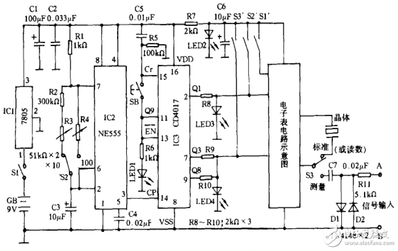
The 9V power supply provides stable 5V for IC2 and IC3 through IC1 voltage regulation. The 5V power is further stepped down by R7 and LED2 to provide 1.5V for the watch. IC2 and IC3 clear the watch and generate standard key pulses of T = N × 10â»Ë£ (e.g., 32.80S and 3.28S). S2 is a gear switch with ×10 and ×100 settings, SB is the measurement button, and S1’–S3’ are the "MODE," "SET," and "ADVANCE" buttons of the watch.
When powered on, the oscillator made from IC2 (NE555), R1–R4, and C3 starts oscillating. IC3 (CD4017) begins counting after being cleared via C5. After a set time, Q9 outputs a high level, stopping the count. Pressing S1’ switches the watch to "running time." The signal under test is connected to A and B, filtered by R11, D1, and D2, and coupled to the watch via C7. Pressing SB resets IC3 and restarts the count. As IC2’s pulse continues, Q1–Q9 of IC3 sequentially output high levels, simulating key presses to control the watch’s timing. At the end of the cycle, the displayed value represents the number of pulses counted during five IC2 cycles, which corresponds to the input frequency.
**Component Selection:**
S1 is the power switch, S2 and S3 are single-pole double-throw switches, and SB is a push-button switch. For stability and accuracy, C3 should be a tantalum capacitor with low leakage and 16V rating. R1–R2 should be 1/4W metal film resistors, while R3 and R4 should be 1/2W 51K linear resistors. A BP-type watch with "running time" functionality is recommended.
**Production and Commissioning:**
Remove the watch’s circuit board, identify its power (+/-) poles and the contacts of the "SET" and "ADVANCE" buttons, and connect them with thin wires. Disconnect one end of the internal crystal oscillator. Connect S3 according to the schematic and fix it to the side of the case. After assembly, adjust R3 and R4 to calibrate the display values at ×10 and ×100 settings.
**Usage and Precautions:**
1. Multiply the displayed value by the gear setting (×10 or ×100) to get the measured frequency in Hz.
2. If the display exceeds 59.99S, multiply by 6000 and add the second digit.
3. Ensure short connections, especially between C7 and S3.
4. Input signals should be less than 1 MHz.
**Function Expansion:**
To measure higher frequencies, add a frequency divider before limiting. Replace components in the oscillator with the component under test to measure its parameters proportionally.
---
**Simple Digital Frequency Meter Circuit Diagram (2)**
This paper introduces a novel RF frequency measurement design using the prescaler SAB6456A and high-speed digital divider 74HC390, combined with the MSP430F449 microcontroller.
**Main Device Introduction – MSP430F449 Microcontroller**
The MSP430F449 features a 16-bit RISC architecture, ultra-low power consumption, and rich on-chip peripherals, including a watchdog timer, comparator, 16-bit timer, serial ports, ADC, and LCD driver. It operates from 1.8V to 3.6V, supports multiple low-power modes, and offers fast interrupt response times. Its Flash memory allows for easy program updates and debugging via JTAG.
**Prescaler SAB6456A**
The SAB6456A is a UHF/VHF prescaler that divides frequencies from 70MHz to 1GHz by 64 or 256, depending on the MC pin state. It has high sensitivity and strong harmonic suppression.
**Working Principle**
The system consists of two main parts: frequency division and counting. The input signal is clipped and divided by the SAB6456A, then further divided by two 74HC390s to produce a low-frequency digital signal (under 10kHz). This signal is fed into the MSP430F449, which uses its internal 16-bit timer A to count pulses and calculate frequency.
**Hardware Design**
Figure 1 shows the front-end processing and frequency division circuit. Two SN74HC390s divide the signal by 100 each, resulting in a total division of 1000. The final frequency is around 4kHz, suitable for MCU counting. Figure 2 illustrates the microcontroller’s peripheral circuit, including reset, power supply, and crystal oscillator. The 8MHz crystal serves as the timer clock, while the 32.768kHz crystal drives the display.
**Software Design**
The divided signal is connected to the MCU’s input. The program waits for stabilization, then counts N pulses in a timer interrupt. The frequency is calculated as N divided by the time interval, multiplied by the division coefficient. Dynamic scanning displays the result on a seven-segment LED.
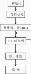
**Main Measurement Procedure**
The code initializes variables, waits for signal stabilization, starts the timer, captures pulses, and calculates the frequency. It then displays the result and repeats the process.
**Conclusion**
The hardware and software have been tested and proven accurate. This low-cost, simple design makes an efficient and economical frequency meter.
**Figure 3: Main Program Flow**
Alumina Ceramic,Alumina Ceramic Ring,99 Alumina Ceramic Ring,Corrosion Resistance Of Alumina Ceramic Ring
Yixing Guanming Special Ceramic Technology Co., Ltd , https://www.guanmingceramic.com