Design of Automatic Control System of Electric Model Based on Single Chip Microcomputer
The C question in the National Undergraduate Electronic Design Competition involves designing an automatic control system for an electric model vehicle, with a single-chip microcontroller at its core. The system uses a reflective photoelectric sensor to collect data and process it through software, enabling real-time speed control of the vehicle as it travels through different sections. A digital display is used to show both the set travel time and the actual time consumed. Infrared communication is employed to transmit time and distance data from specific zones—such as speed limit areas, endpoint zones, and return-to-start zones—to a handheld device. The system also includes a keyboard installed on the car, allowing for more convenient and precise speed adjustments.
The main goal of the design is to achieve speed control along a predefined route, adjusting the vehicle’s speed according to different driving sections. To ensure the car remains aligned with the track, an infrared digital sensor is integrated to enable accurate positioning. Below is a detailed explanation of how the system is implemented.
1. Data Acquisition Scheme Selection Data acquisition can be achieved using several methods: (1) a combination of LEDs and phototransistors; (2) infrared LEDs and receivers; or (3) laser technology. In this design, we opted for the second method due to its suitability for close-range detection. Infrared light has a longer wavelength than visible light, making it less susceptible to interference from ambient light. It also offers advantages such as compact size, low power consumption, and minimal impact on human eyes. However, it may suffer from signal attenuation in humid environments or under fog, which limits its use to indoor settings. The selected reflective photodetector is small, highly sensitive, and easy to install, making it ideal for proximity sensing.
2. Display Device Selection For on-board display, a digital tube is used to show the elapsed time and the set time during the journey.
3. Communication Mode Selection Communication can be done via radio or infrared. While radio allows for longer distances, it requires a more complex circuit. Infrared, on the other hand, is simpler and suitable for short-distance transmission. Since only one-way communication is needed, we chose infrared as the transmission medium.
4. Power Supply and Vehicle Weight Considerations To address issues like motor power, vehicle weight, and friction resistance, components were selected based on low power consumption, compact size, and lightweight. The power supply consists of six 5th batteries connected in series to provide a 9-volt DC power source.
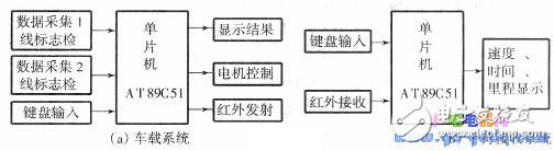
The diagram above illustrates the system's block structure. The photoelectric sensor detects various flags and sends signals to the microcontroller via the INTO and Tl ports. The microcontroller processes these signals and adjusts the motor speed by sending output signals through the Pl.1 port. Once the vehicle returns to the start point, the MCU outputs the traveled distance and time through the serial communication port. Additionally, at designated locations, the MCU transmits data to a handheld receiver via infrared through the Pl.7 port. This handheld device, also controlled by a microcontroller, allows real-time tracking of the vehicle’s position and time. The keyboard enables parameter setting during testing, improving the accuracy of speed and location control.
TM-3C Series (10.1"-27")
Multi Touch Display Monitor,Outdoor Touch Screen Monitor,Waterproof Touch Monitor
HuiZhou GreenTouch Technology Co.,Ltd , https://www.bbstouch.com